One common issue that is often faced by an engineer designing the onboard CAN bus in a vehicle is that the recommended bus topology is often difficult to reconcile with the constraints imposed by the design of the vehicle. Ideally, the vanilla CAN bus should arrange nodes in a daisy chain fashion terminated at both ends, with the stub length minimized to reduce reflections. The reflections are undesirable because they induce ringing on the bus, which may lead to packet loss with subsequent retransmission and delays.
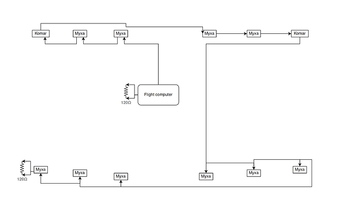
The following diagram illustrates one possible wiring arrangement on a tandem aircraft with 12 motor controllers (labeled Myxa and Komar in this example), three per wing section:
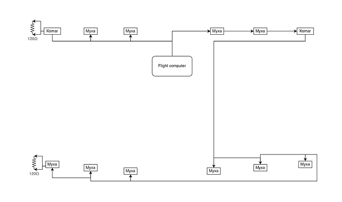
While this is a functional arrangement that is in line with the CAN bus wiring recommendations, it is deficient in the sense of the total length (and thus mass and cost) of the cabling required. One obvious way to improve it, as shown below, is often hampered by the poor design of the CAN interface in many (should I say most?) modern UAV flight controllers, where the flight controller incorporates a CAN bus termination resistor that is impossible to disable. Yours truly had a conversation on this with the Pixhawk hardware team back in May 2014 but no progress was made at the time, and it remains one of my pet peeves since. As such, while this solution would be superior to the above, it is often not a viable one:
Please do urge your flight controller vendor to get rid of the built-in CAN terminator for the greater good.
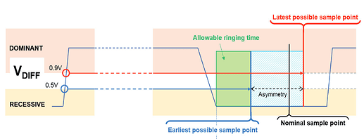
The topology problem was recognized by the CAN in Automation (CiA) group years ago, which culminated in the development of the CiA 601 specification on CAN signal improvement. The objective is to provide enhanced capabilities in the CAN transceiver chips that would actively suppress the ringing on the line induced by reflections. One approach is to make CAN transceivers detect the dominant-to-recessive transition early and then actively drive the line towards the recessive state by shorting CAN H and CAN L via a dedicated switch, which will cause the ringing to decay faster.
16-1_p12_ringing_suppression_in_can_fd_networks_denso_mori.pdf (6.8 MB)
19-4_p18_cia_601-4_can_signal_improvement_tony_adamson_nxp.pdf (2.2 MB)
(image from “CiA 601-4: CAN signal improvement”, Tony Adamson, NXP Semiconductors, 2019)
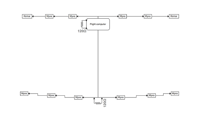
Such methods of active signal improvement are not accessible to the integrator since CAN transceivers are not really replaceable. However, another obvious way forward is, indeed, often accessible and should be evaluated: the ringing is acceptable as long as it decays sufficiently before the bit is sampled. It follows that if the current bus topology is ailed with reflections, reducing the bit rate may help. This occasionally makes simple mixed bus/star topologies as shown below admissible, provided that the network is compact enough:
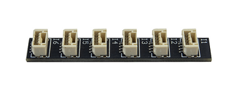
Passive CAN bus splitters will work well in this case. For instance, here’s one compatible with the Dronecode Autopilot Connector Standard (image is taken from https://www.unmannedtechshop.co.uk/product/can-bus-splitter-hub-board/):
Per the CiA recommendations, the maximum single stub length and the maximum total stub length at 125 kbit/s are 22 m and 110 m, respectively.
Shall the mixed topology be inadmissible (perhaps for reasons of size, complexity, or the required data rate), one might resort to a repeater or a store-and-forward bridge (various sources use different terminology).
A repeater is a device combining two CAN transceivers connected back-to-back with a simple arbitration logic in between. There is occasionally also galvanic isolation built in between them.
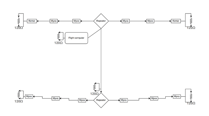
A pair of repeaters allows us to improve the design as follows, splitting the bus into three physical segments, each having a pair of terminators:
Here is an instructive reference design from Texas Instruments: TIDA-01487 Isolated CAN FD Repeater Reference Design (1.9 MB)
Beware that a repeater may introduce a significant delay due to the two transceivers and the additional logic in between them. Say, the cable propagation delay assumed by some CiA standards is 5 ns/m. If the end-to-end latency of a repeater amounts to, say, 120 ns, adding a repeater may be considered the equivalent of adding 24 meters of extra cable.
A store-and-forward bridge acts as a regular CAN node with two CAN interfaces, forwarding traffic between them. This is reminiscent of a switched network rather than a bus, and it does come with obvious disadvantages such as increased latency. This is a different kind of latency though: the bus segments are effectively decoupled by the bridge so the signal propagation delay is a non-issue, but the frame forwarding latency may become significant at the application layer depending on its own constraints.
Possible benefits of using a bridge are that the bridged bus segments may operate at different bit rates, and the bridge may be configured to selectively filter traffic between the segments.
There are multiple COTS options available from different vendors, e.g., Helmholz, Ixxat, Guangcheng.
Tunneling is a more extreme variation of the above, where the CAN frames are teleported to a remote CAN bus segment by way of another (faster) transport:
One Cyphal-specific option is currently being discussed in a separate thread on this forum: Cyphal/UDP Routing over Multiple Networks
Also, using SocketCAN on GNU/Linux with can-utils, one can build a tunnel from can0 to can1 using can-gw as follows:
sudo modprobe can-gw
sudo cangw -A -s can0 -d can1
figures.dia (6.1 KB)
