L3X-Z - A OpenCyphal enabled hexapod robot for ELROB 2022

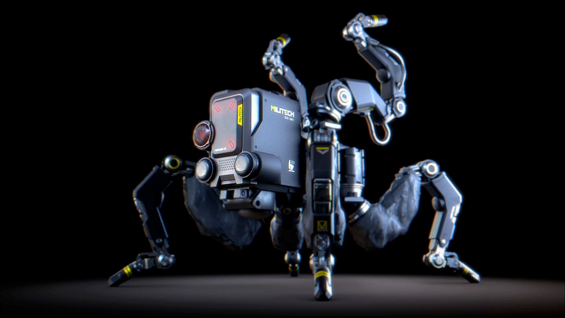
TL;DR: We’ve¹ built and deployed a six-legged electric/hydraulic hexapod robot utilizing OpenCyphal at ELROB 2022, a long-running robot competition with a focus on military applications.

2022-05-31-ELROB-2022-Alex-08

Background

Last week this years ELROB (European Land Robot Trial) took place at the ABC- & Katastrophenhilfeübungsplatz (a Austrian army training ground) “Tritolwerk” in Eggendorf, Wiener Neustadt, AUSTRIA. The purpose of ELROB which alternates between civilian and military focused testing scenarios is to provide a real-world testing ground for robotic systems both under active development and already in production.

L3X-Z is a six-legged mixed electric/hydraulic hexapod robot built for participating in the “Reconnoitring of structures” scenario under the 107-systems label. This scenario requires exploring an unstructured environment in combination with map building and detection and location of objects of interest.

System Overview

Rasperry Pi 4
|-- USB
   |-- OpenMV Colour Camera
   |-- OpenMV Thermal Camera
   |-- Intel Realsense D435i
   |-- USB-2-RS485 (U2D2)
       |-- 6 x Dynamixel MX-28
       |-- 2 x Dynamixel MX-28 for pan/tilt head (containing thermal/colour camera)
   |-- USB-2-RS232
       |-- Scanse Sweep 2D LIDAR
   |-- Lynxmotion SSC-32 Servo controller for hyraulic valves
   |-- USB-2-CAN (Zubax Babel) for OpenCyphal
       |-- Zubax Orel 20 for driving the hydraulic pumps BLDC motor
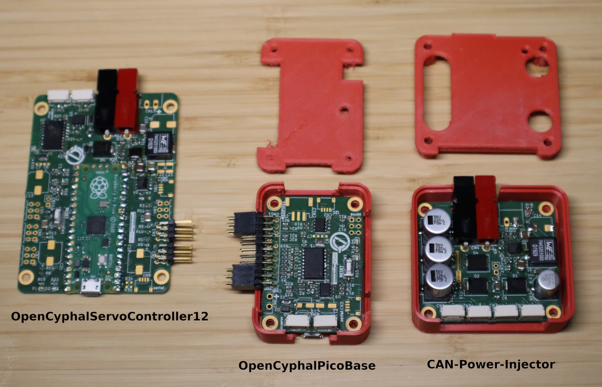
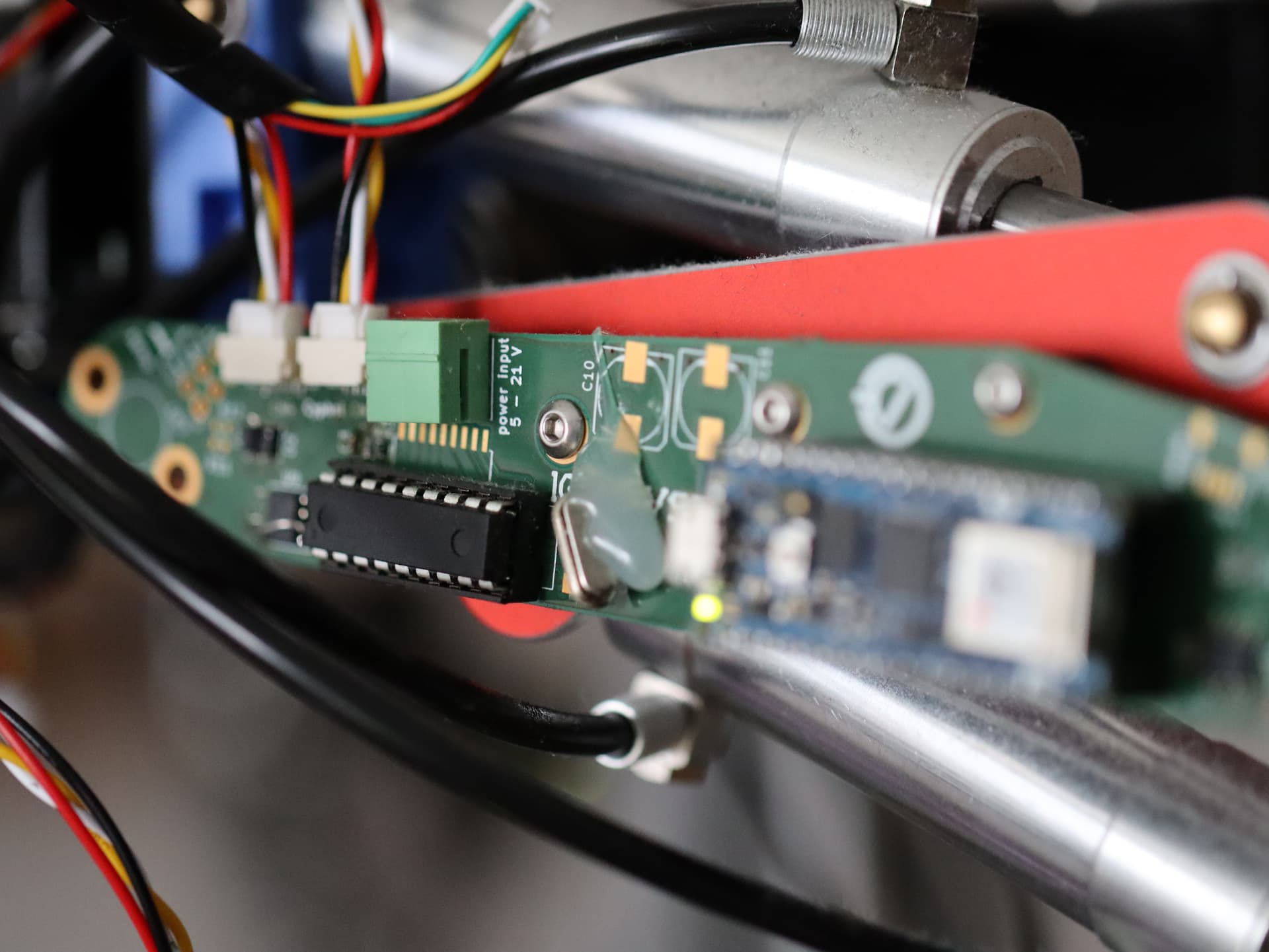
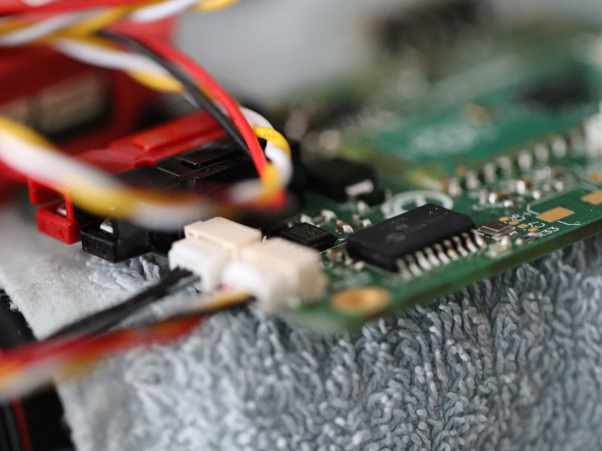
       |-- 6 x Leg Controller Board (for sensing leg angles via magnetic rotary encoders and ground contact)
       |-- 1 x Radiation sensor providing reading of local radioactivity levels (connected via OpenCyphal)
       |-- 1 x Auxiliary controlloer for various IO tasks (connected via OpenCyphal)

System Description

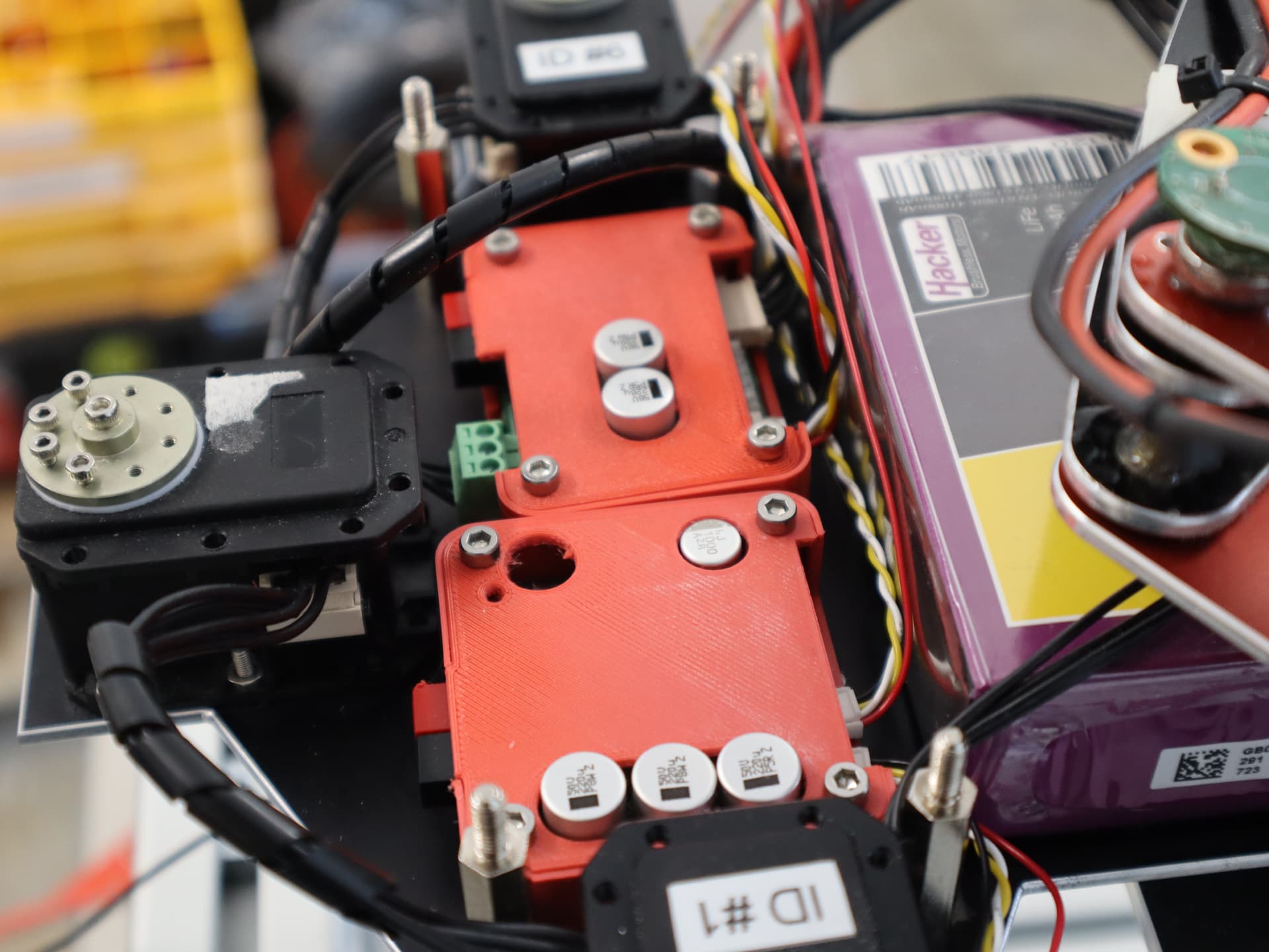
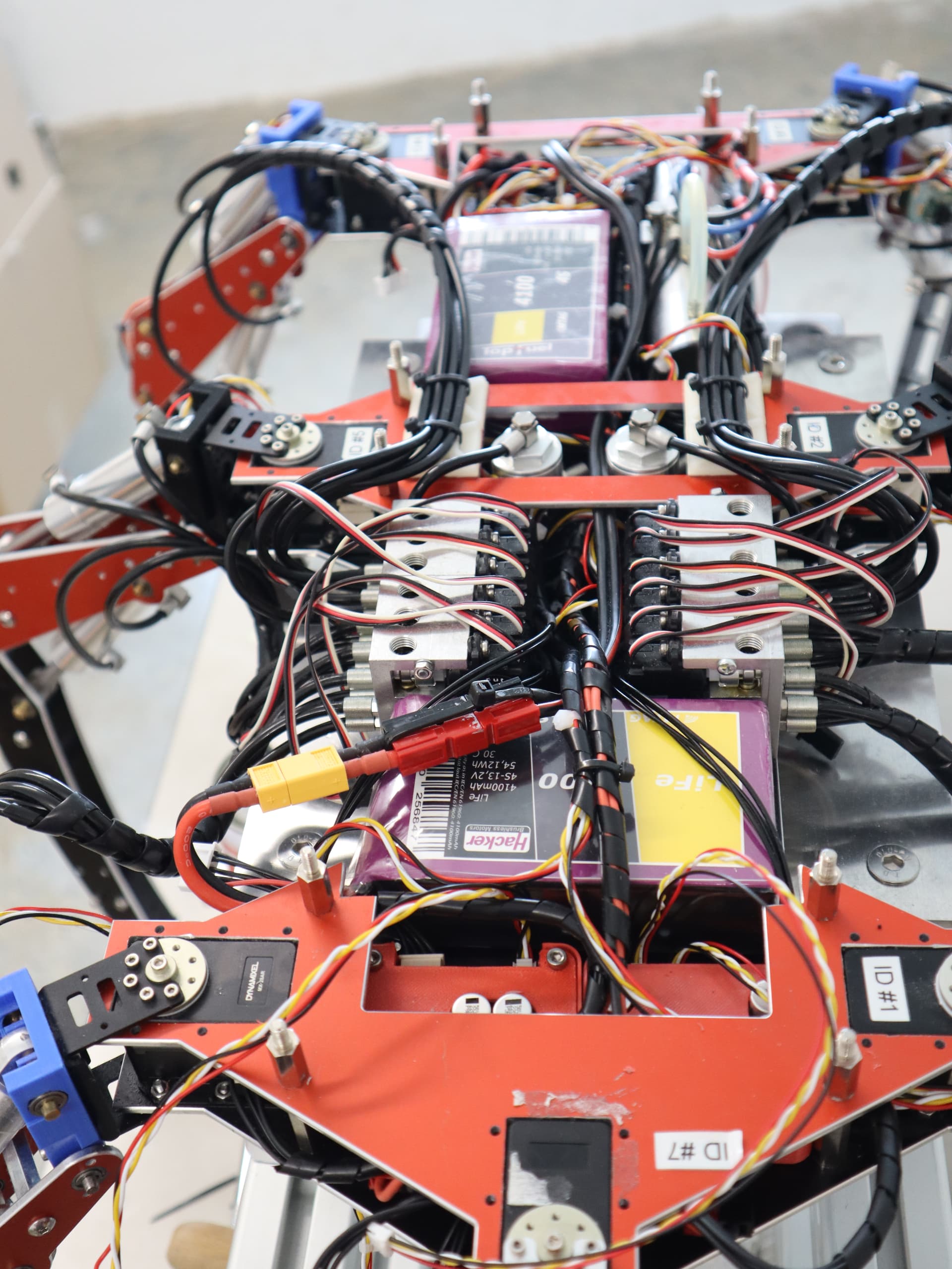
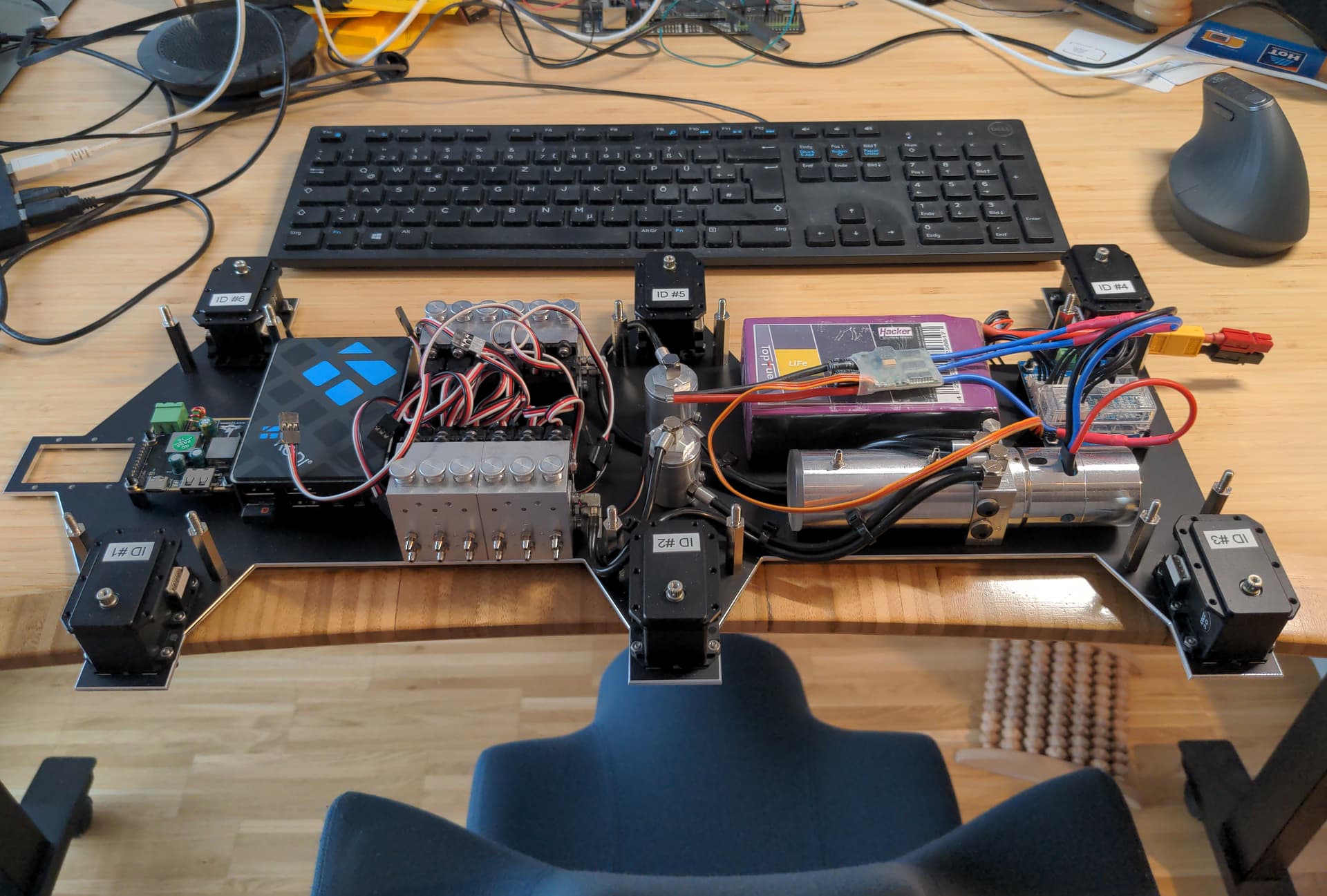
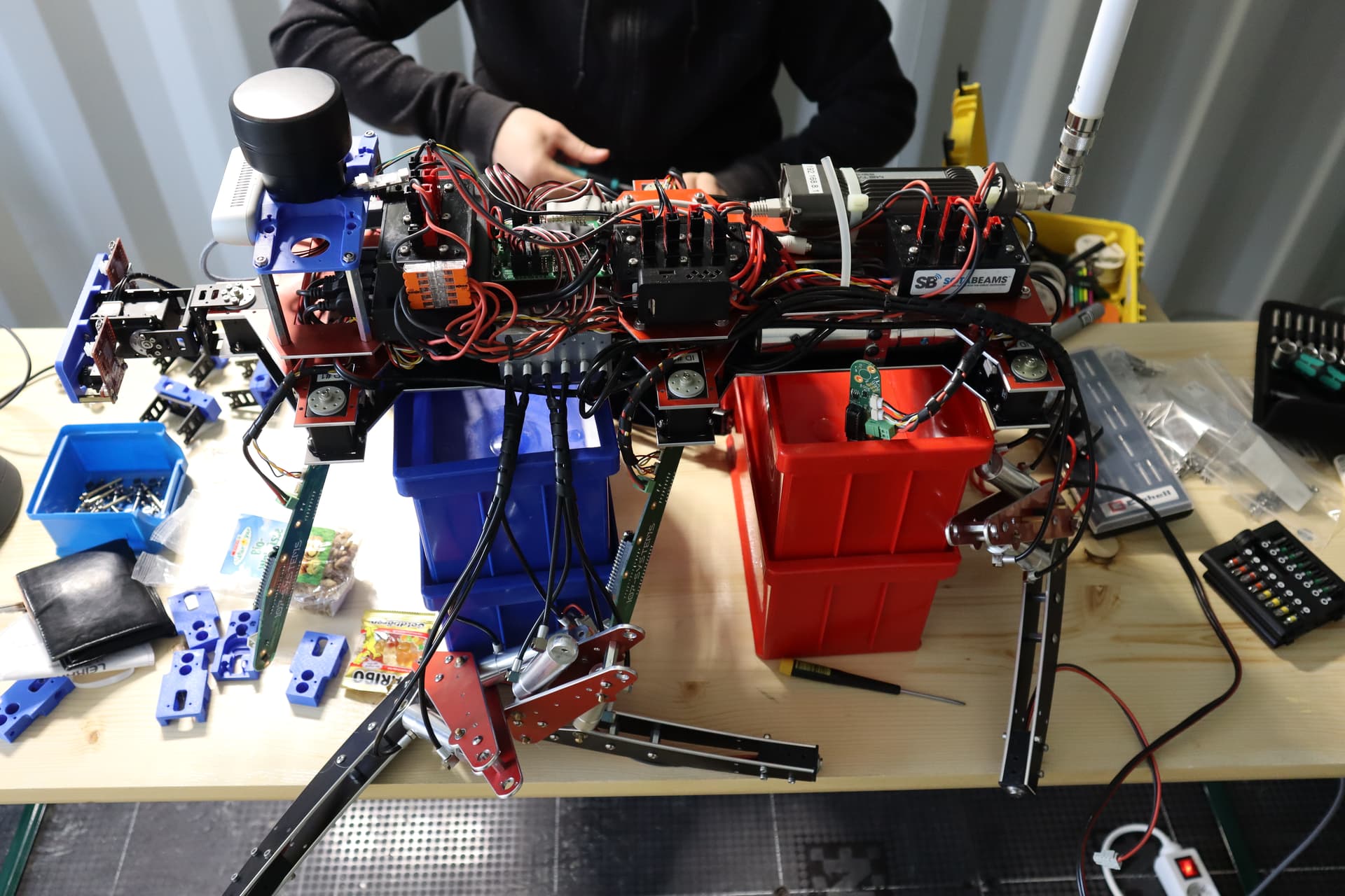
This picture at an early building stage shows the dual pressure circuit hydraulic pump behind the 4S LiFePo battery, the 6 Dynamixel MX-28AR coxa (hip) servos, the USB-2-RS485 converter (behind the battery), the RC servo actuated valve blocks and the Rasperry Pi 4 power supply (PCB to the front).

2022-03-31-L3X-Z-02

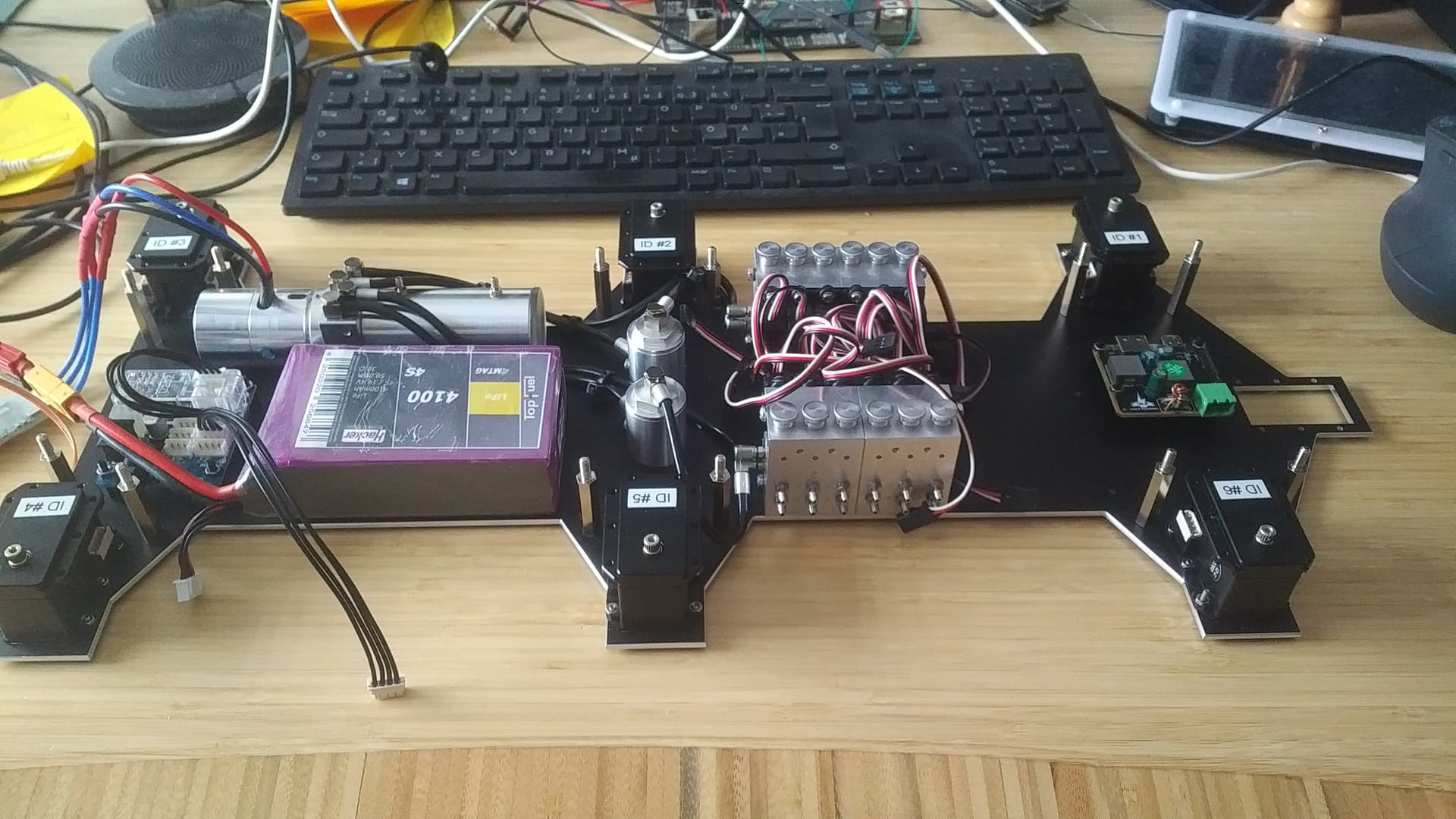
On the next image the Raspberry Pi 4 has already been mounted. One can also see the stock supplied ESC which unfortunately died on the test bench. Consequently it was replaced with a Zubax Orel 20 and while I’m not paid by @pavel.kirienko to write this I’ve got to say that the products of Zubax Robotics have a “just works” quality to them that is hard to undervalue.

2022-04-01-L3X-Z-01

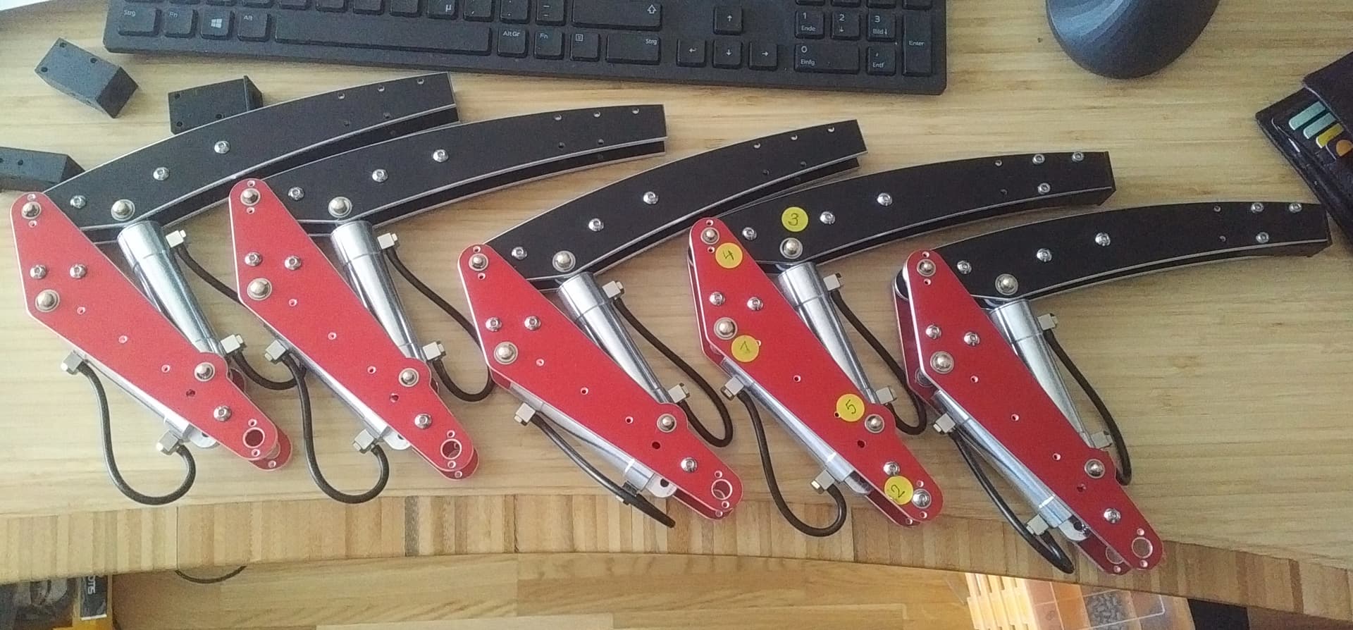
The next image shows 5 fully assembled robot legs. While the coxa (hip) is actuated by a electric servo femur (thigh bone) and tibia (shinbone) are actuated via hydraulic cylinders. The reason behind choosing hydraulic actuators are twofold:

  1. Classic electric, geared servos handle the strain of a heavy weight hexapod quite badly, leading to a short servo live-span.
  2. There’s zero power required for the legs to hold their position when the valves are shut off.

2022-04-20-L3X-Z-01

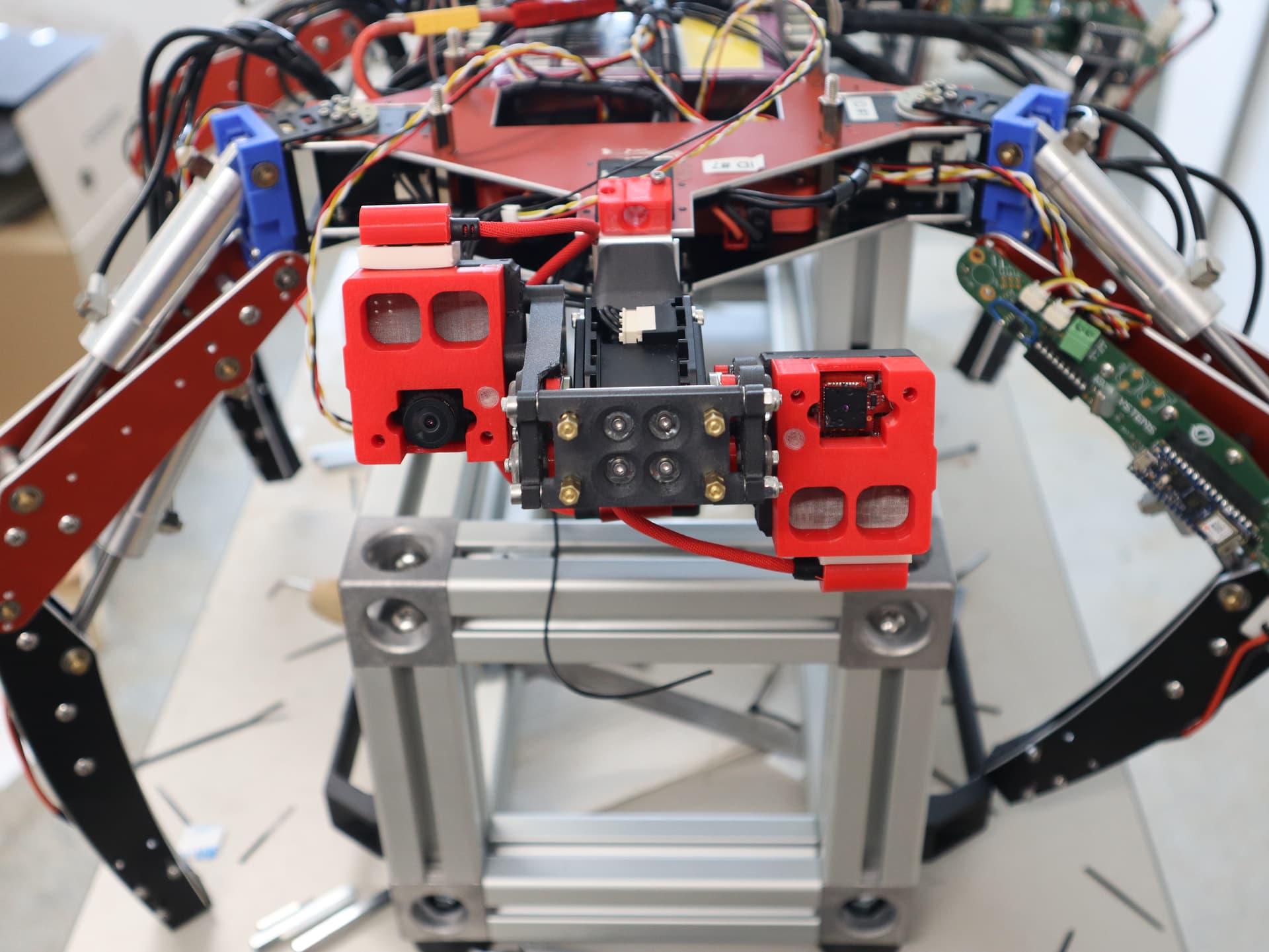
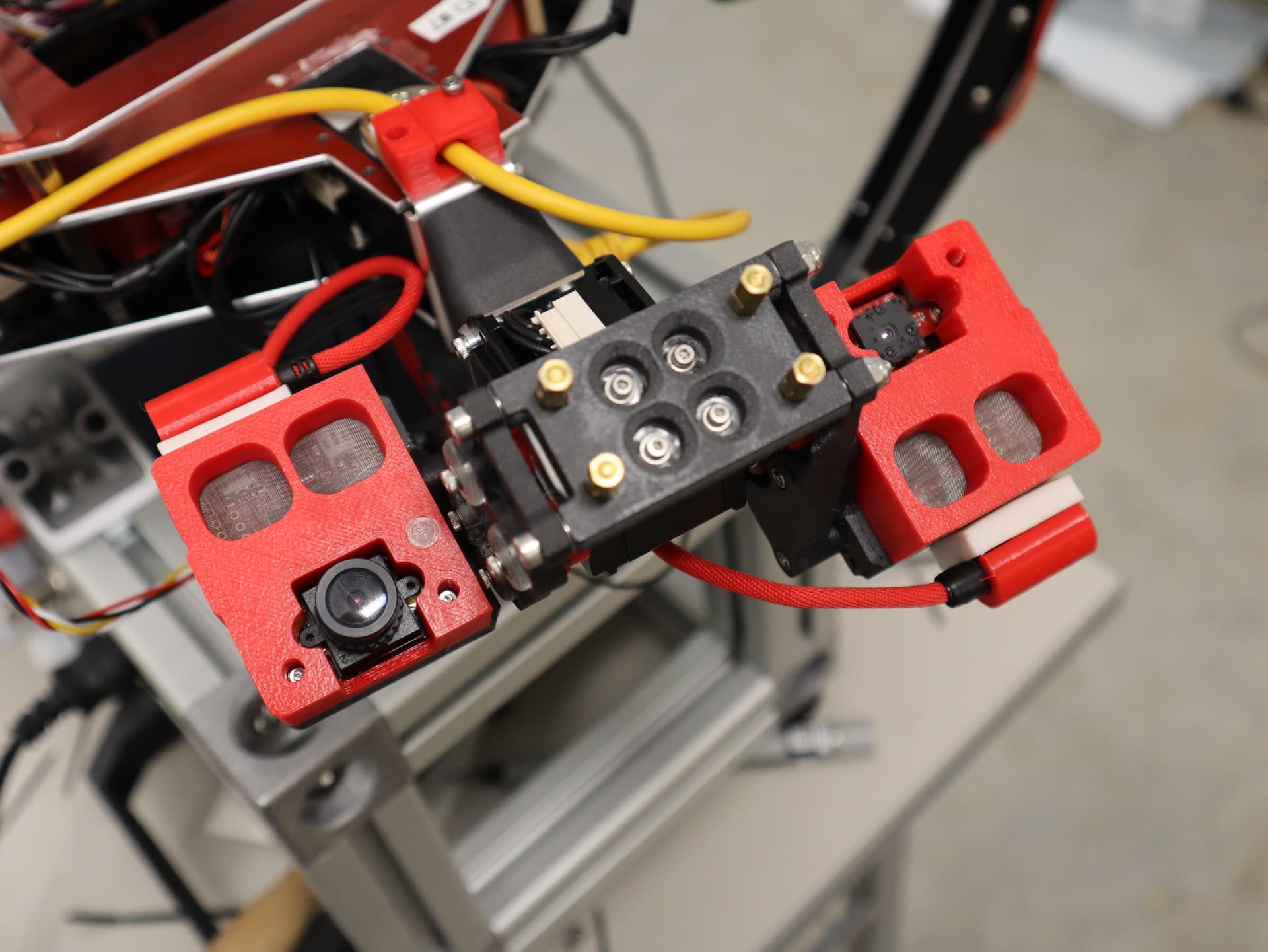
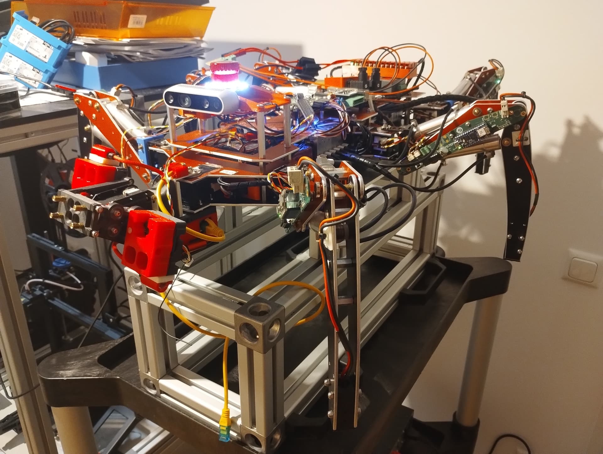
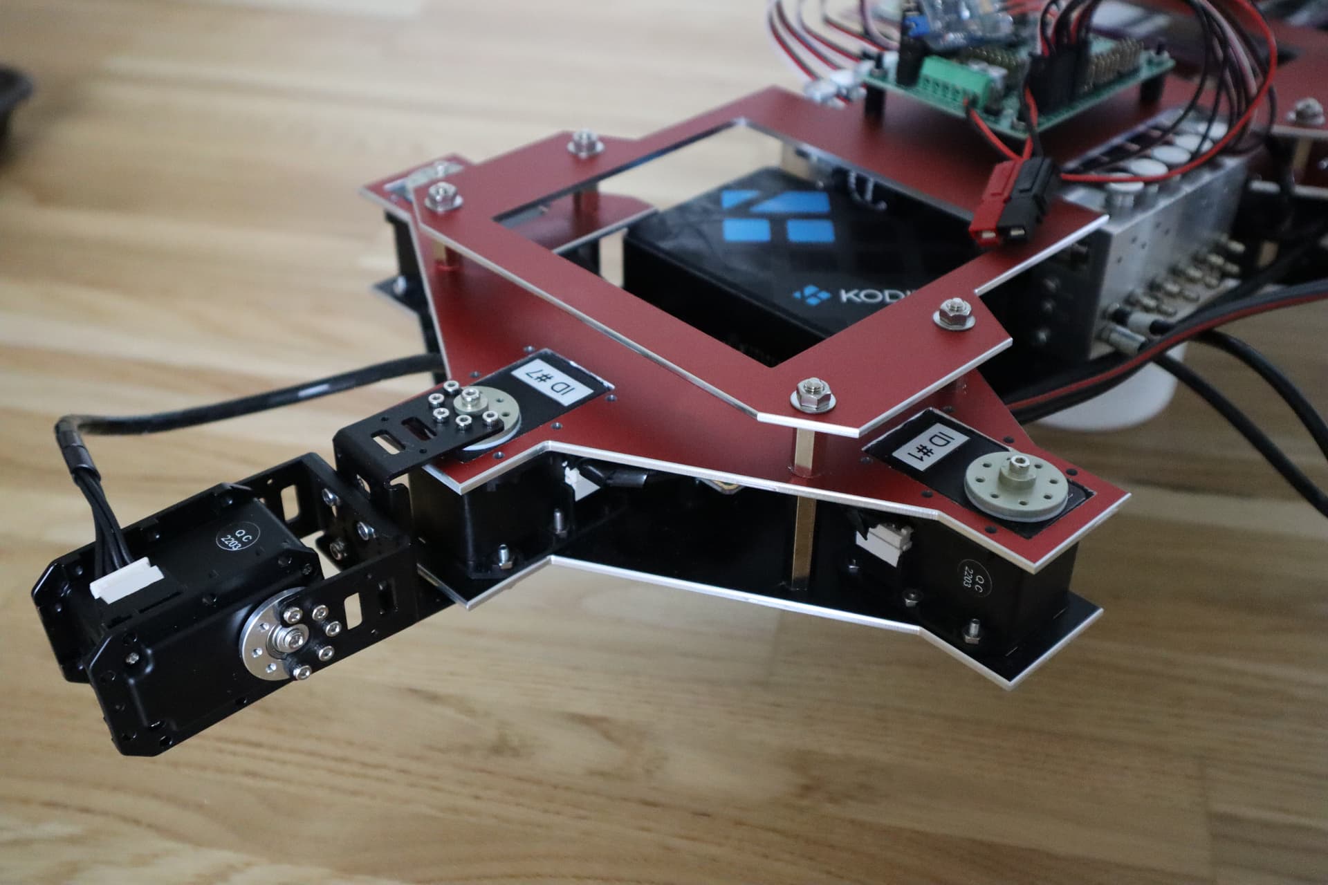
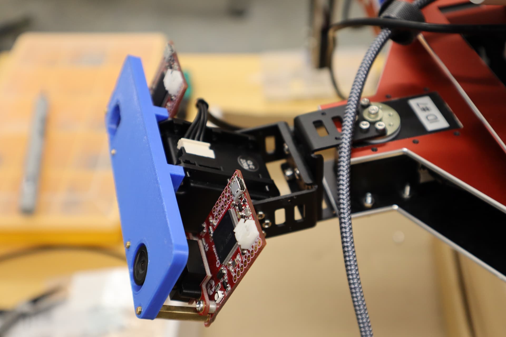
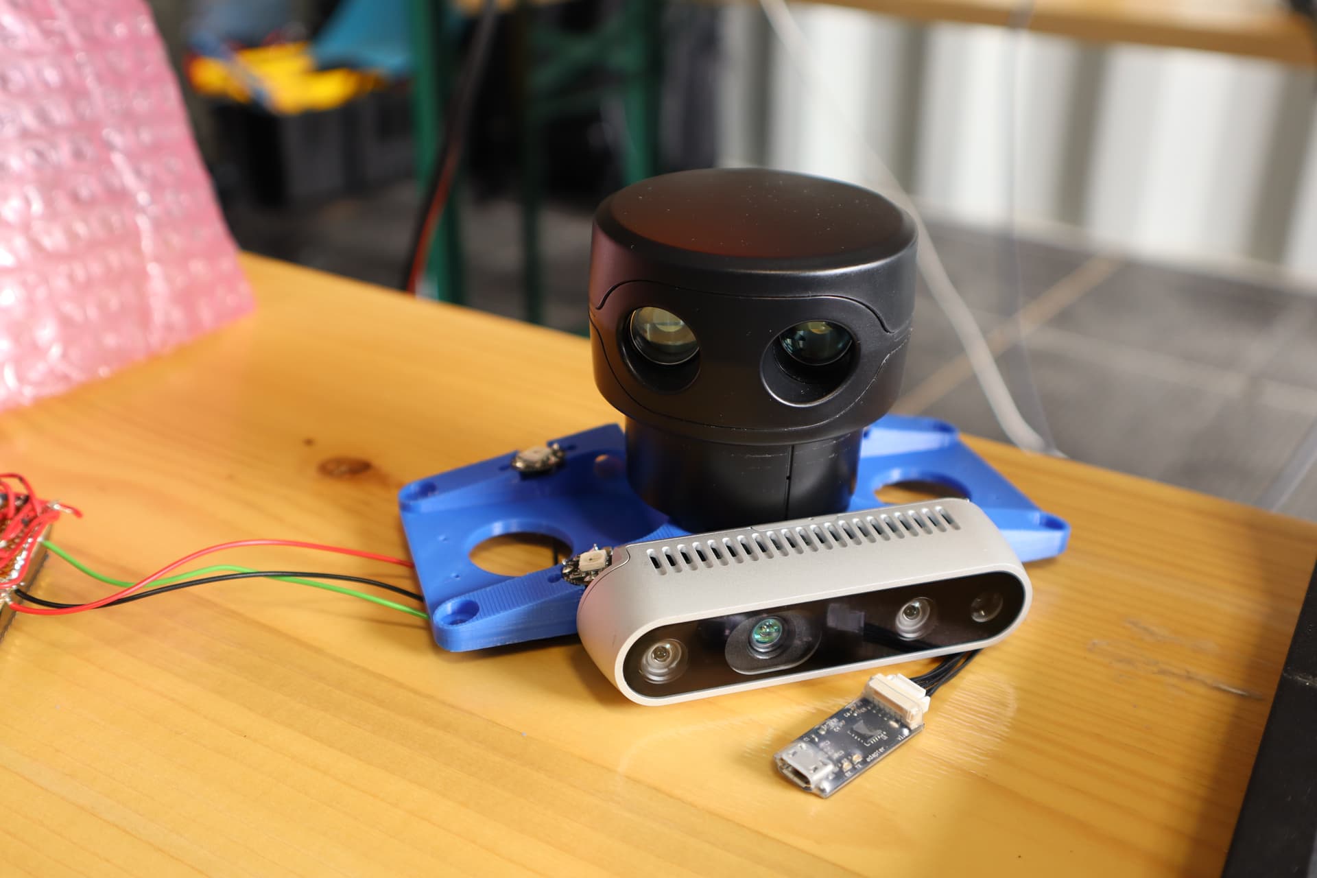
The next image shows the pan/tilt head to which later the thermal and colour cameras (used for remote robot control) will be mounted.

2022-04-22-L3X-Z-01

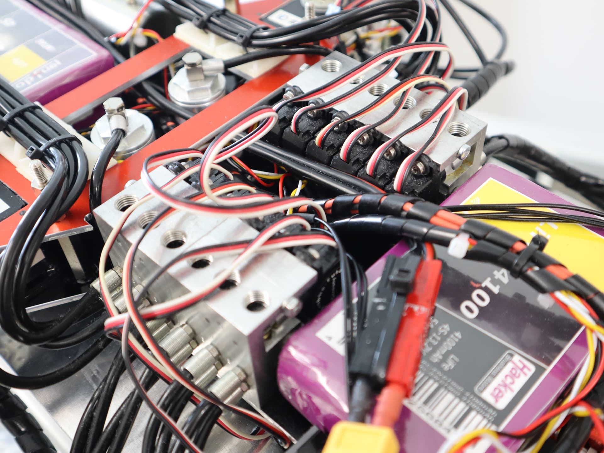
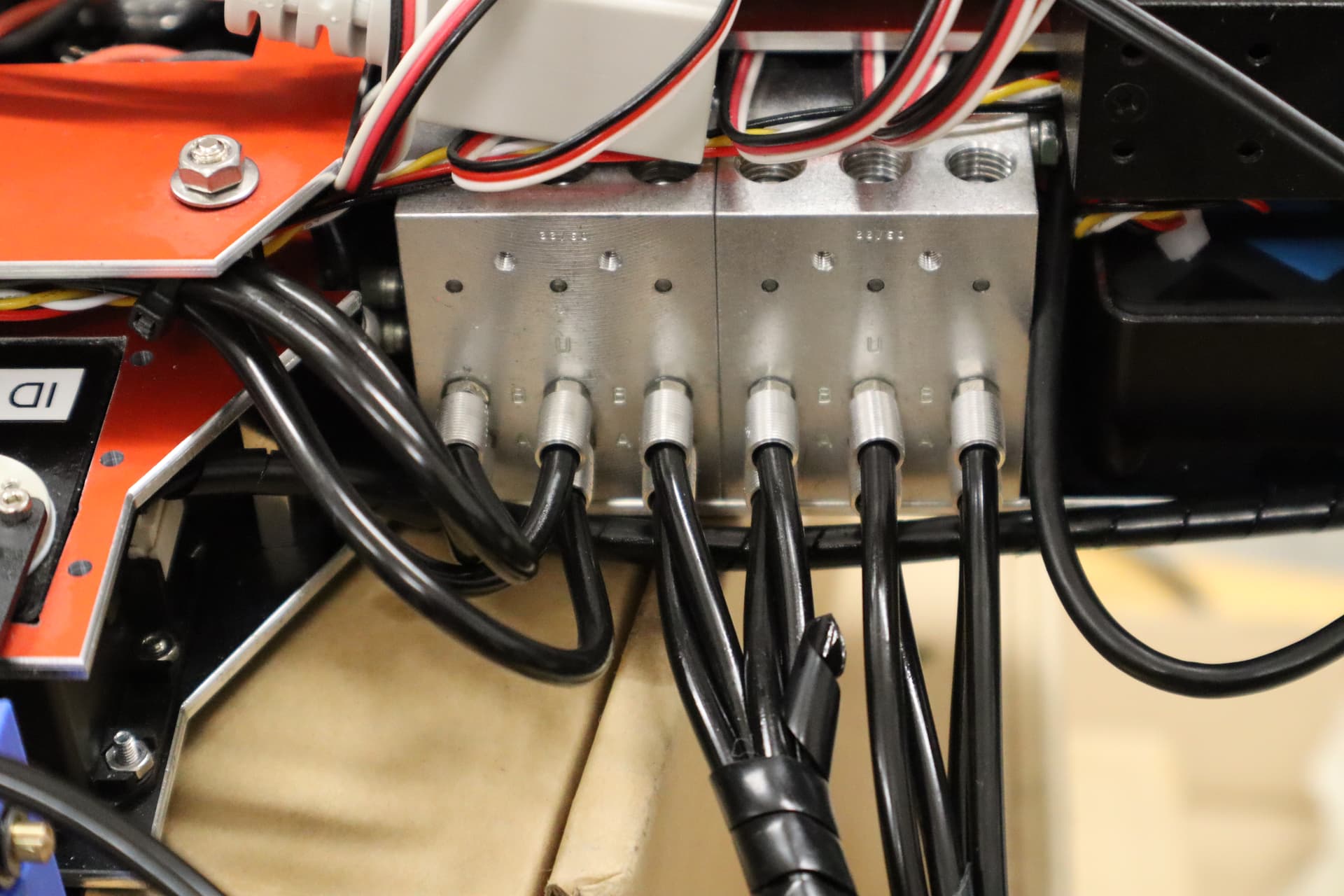
A Lynxmotion SSC32-U (barely visible under all those wires on top of the valve blocks) is used for controlling the RC servos which in turn control direction and flow volume through the 12 hydraulic valves.

For wireless connection a MikroTik RBMetal5SHPn (grey box with white antenna) is being used. Those routers, which enjoy considerably following within the ham radio community provide up to 1.3 W TX power which is considerably higher than what your typical consumer-grade WiFi router can provide. Within the ham radio community those routers are typically used for wide-distance point-to-point connections, i.e. for HAMNET.

2022-04-22-L3X-Z-05

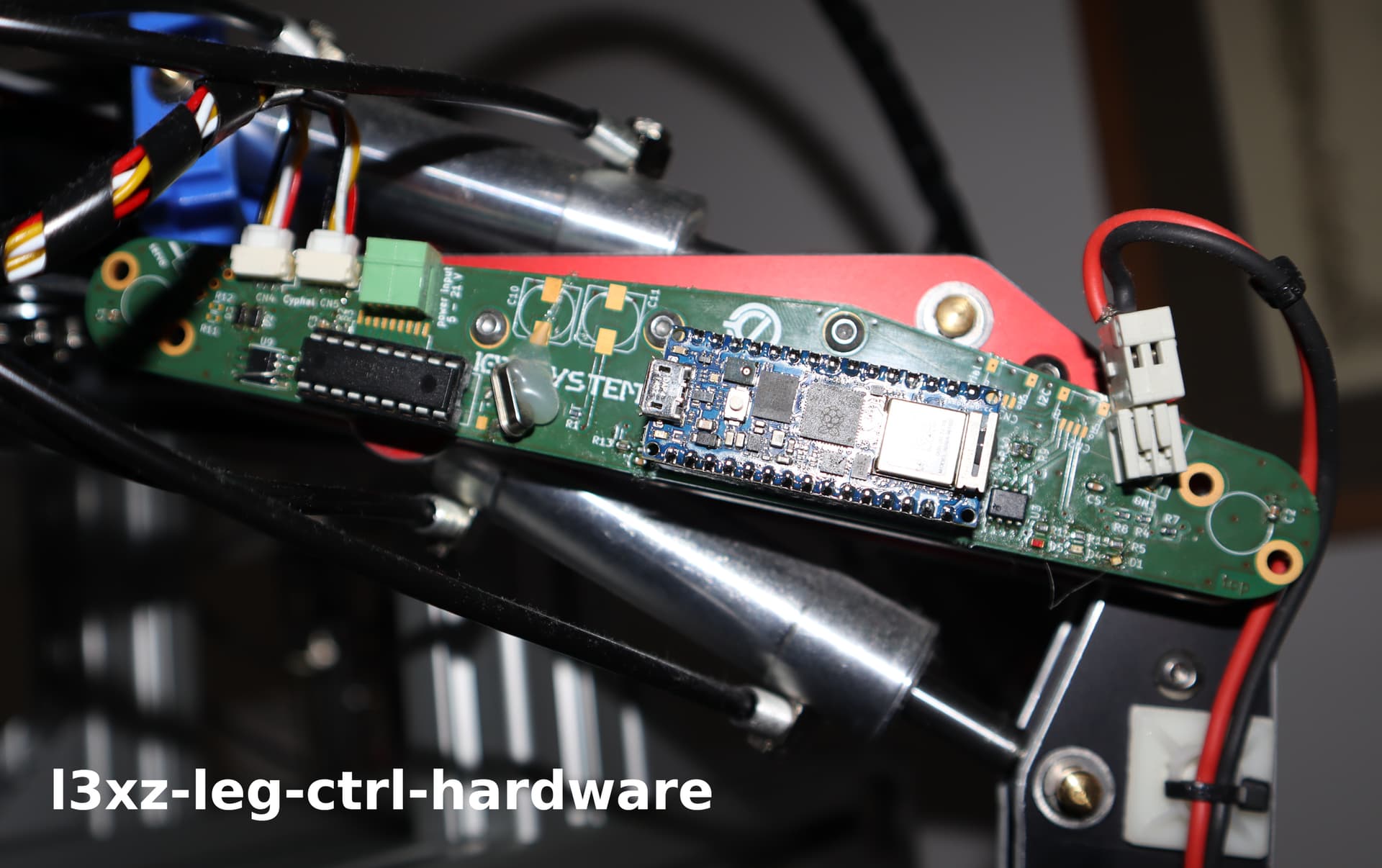
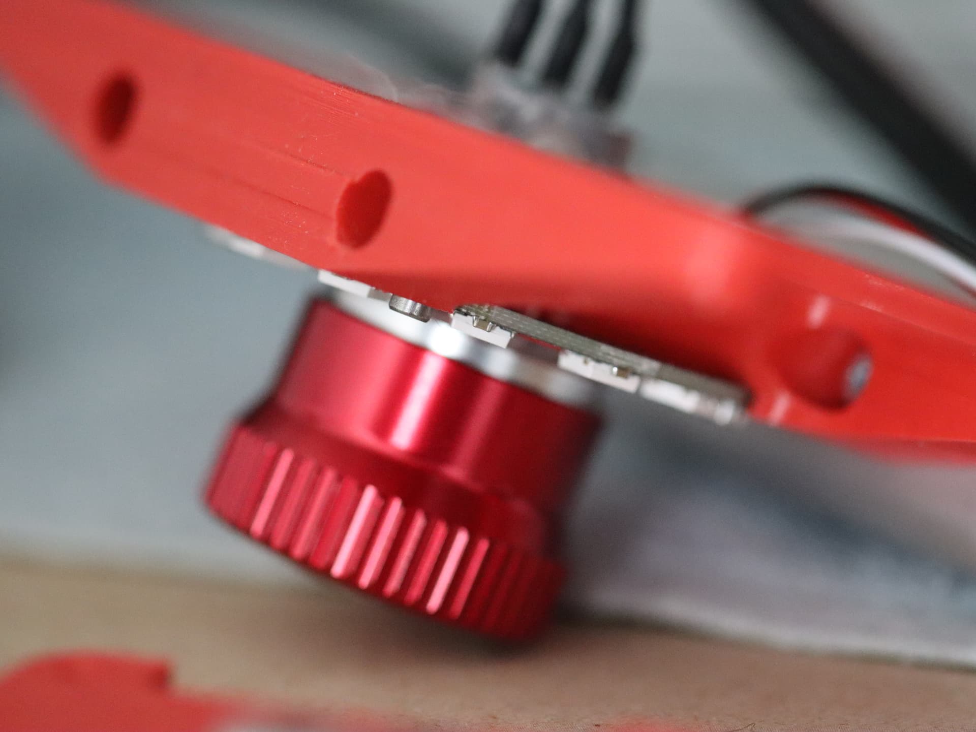
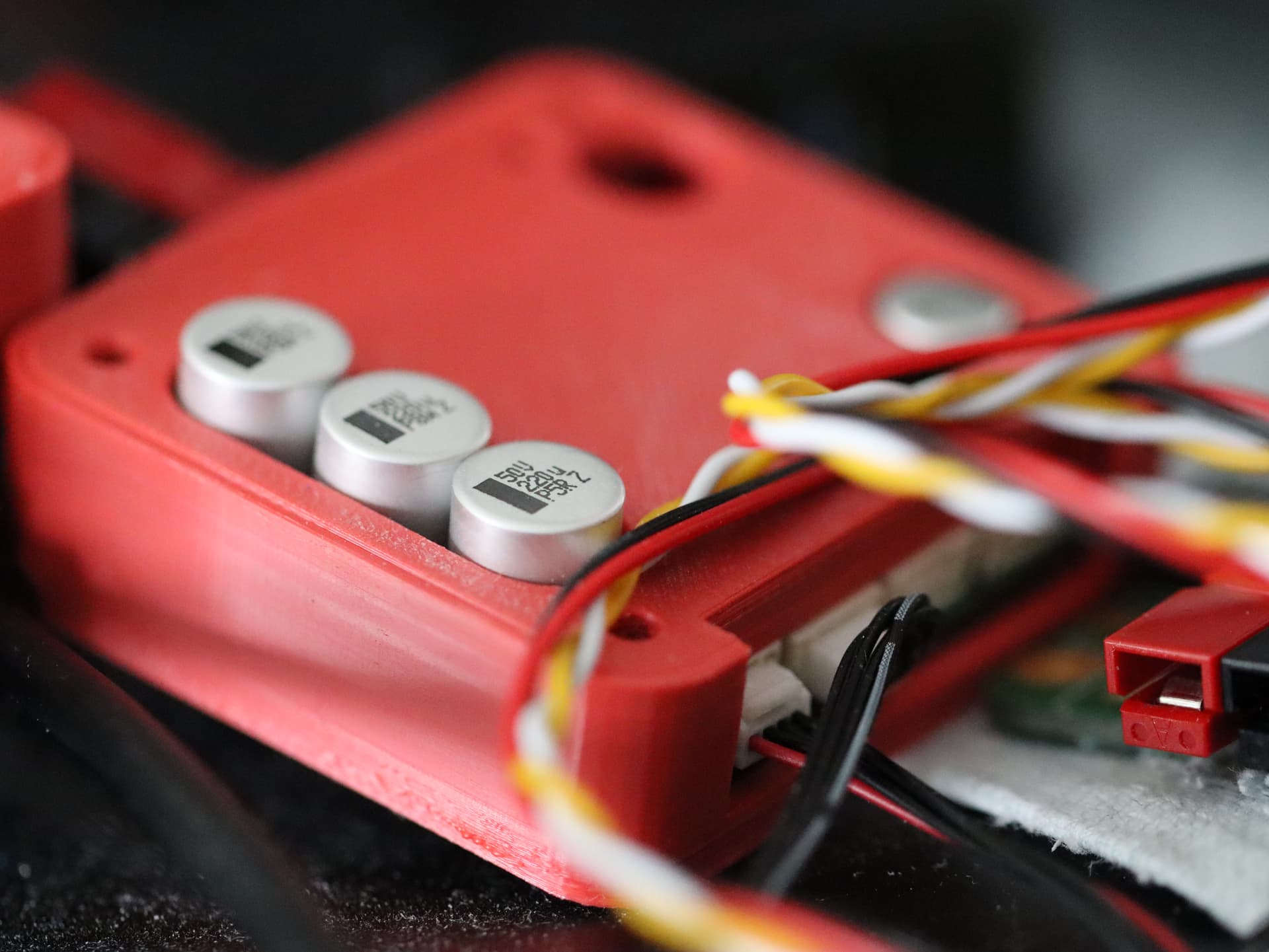
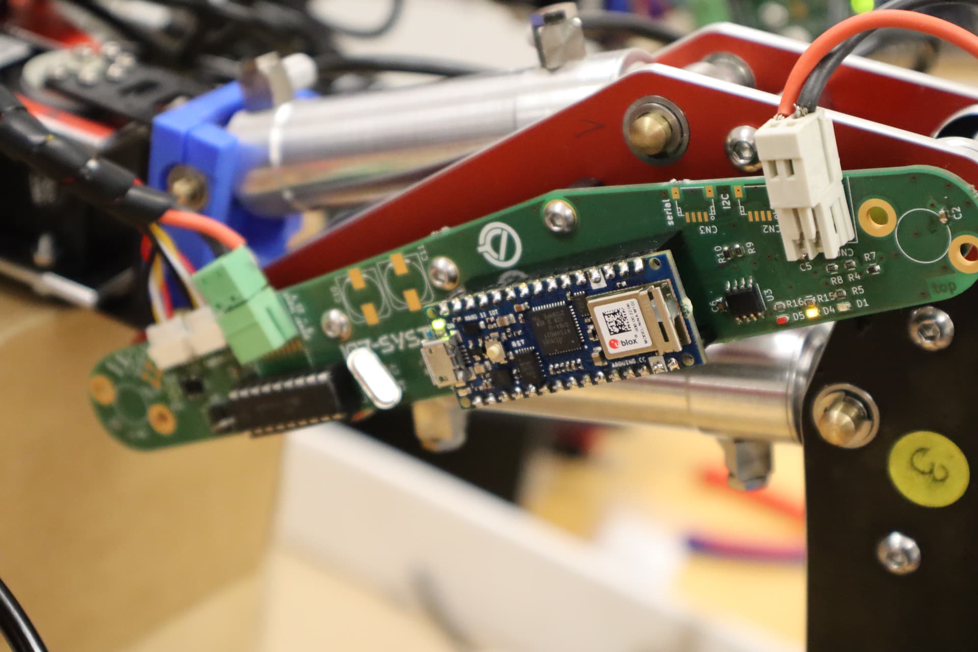
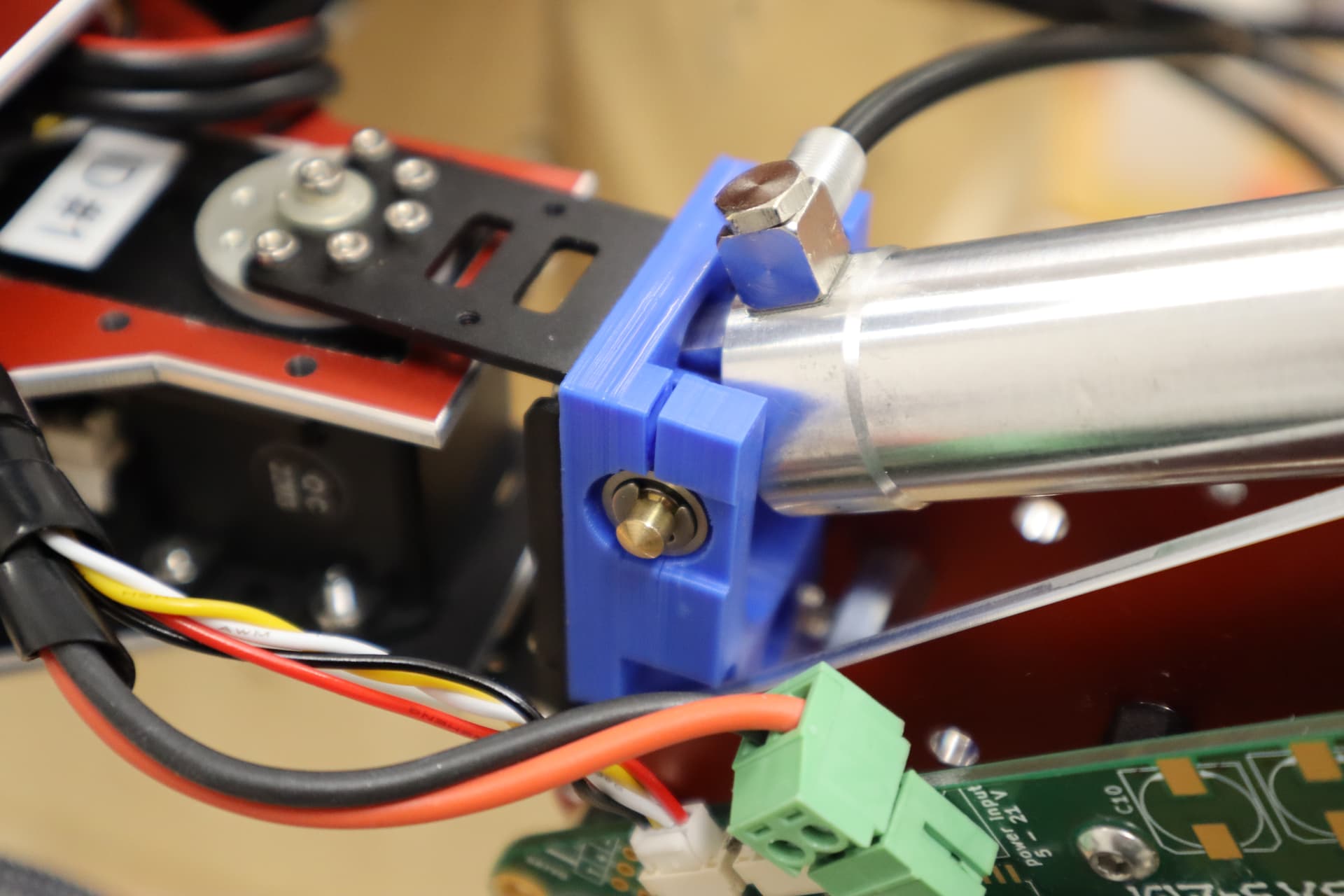
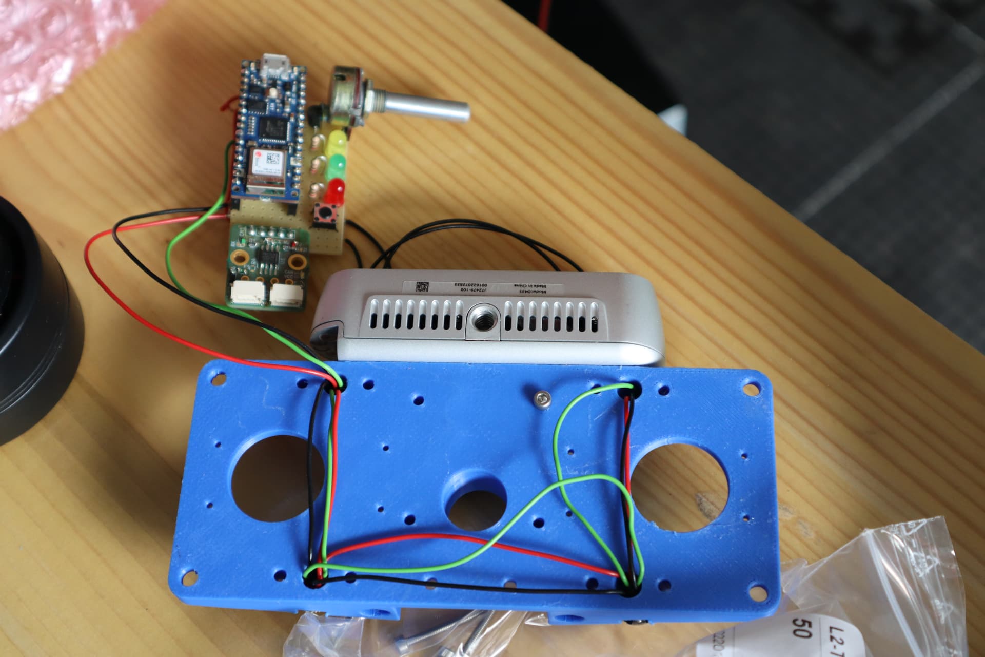
While the Dynamixel coxa servos are “smart” (meaning they provide information about the current actuator angle as well as allowing to set a target angle) the hydraulic cylinders are purely mechanic actuators. In order to obtain the current angle of both femur and tibia joint a small diametric magnet is glued on the shafts of the axis we wish to observe.

2022-05-16-L3X-Z-01

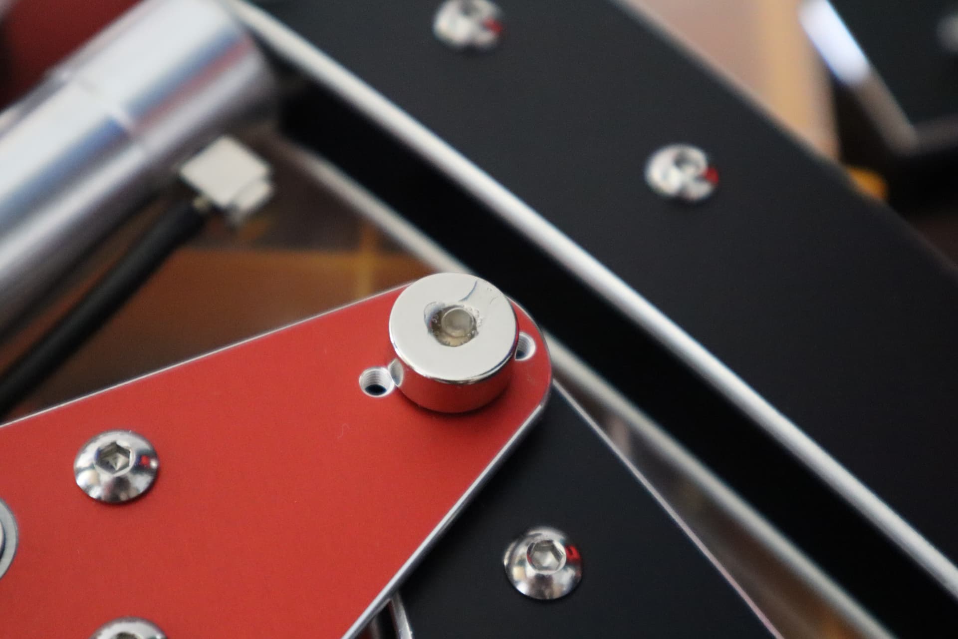
The rotation of the magnetic field is picked up by magnetic rotary encoders and is pre-processed, encoded and transmitted to the control software within the Raspberry Pi 4 via OpenCyphal/CAN utilizing a batch of pre-existing Arduino libraries (i.e. 107-Arduino-UAVCAN - will receive a workover to OpenCyphal shortly, 107-Arduino-MCP2515, 107-Arduino-AS504x, etc.).

2022-05-23-L3X-Z-24

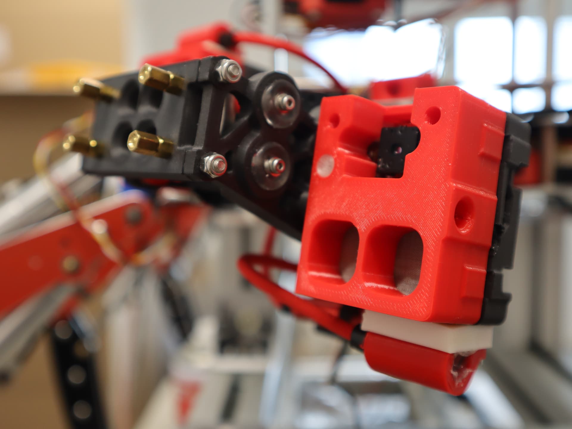
On this image both colour and thermal camera have been mounted to the 3D printed pan/tilt head:

2022-05-23-L3X-Z-12

Connecting all hydraulic lines was quite a ton of work. One of the things we wish to improve in the future is to plan hydraulic lines into the hardware design, which should lead to a much cleaner overall wiring situation.

2022-05-23-L3X-Z-23

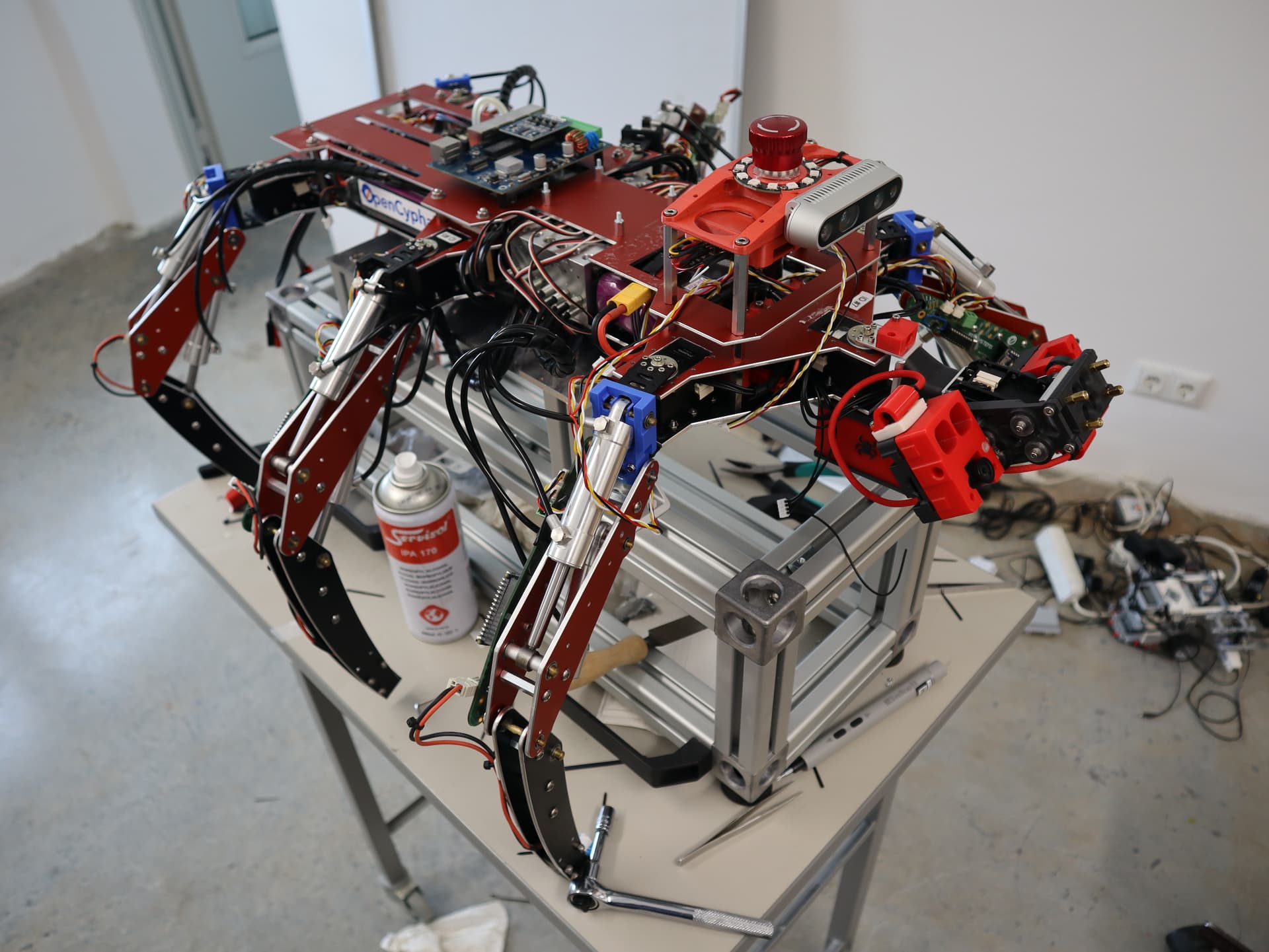
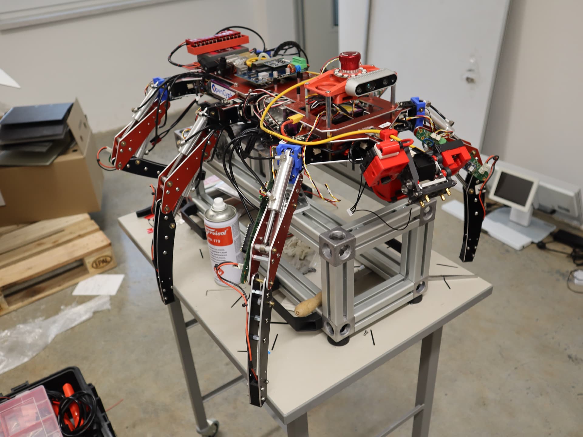
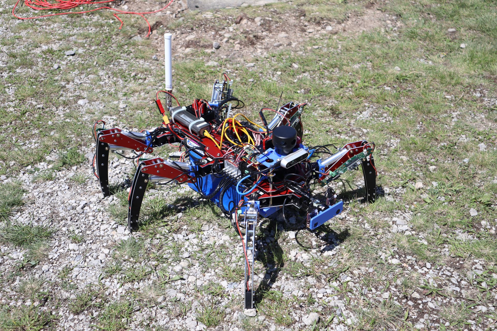
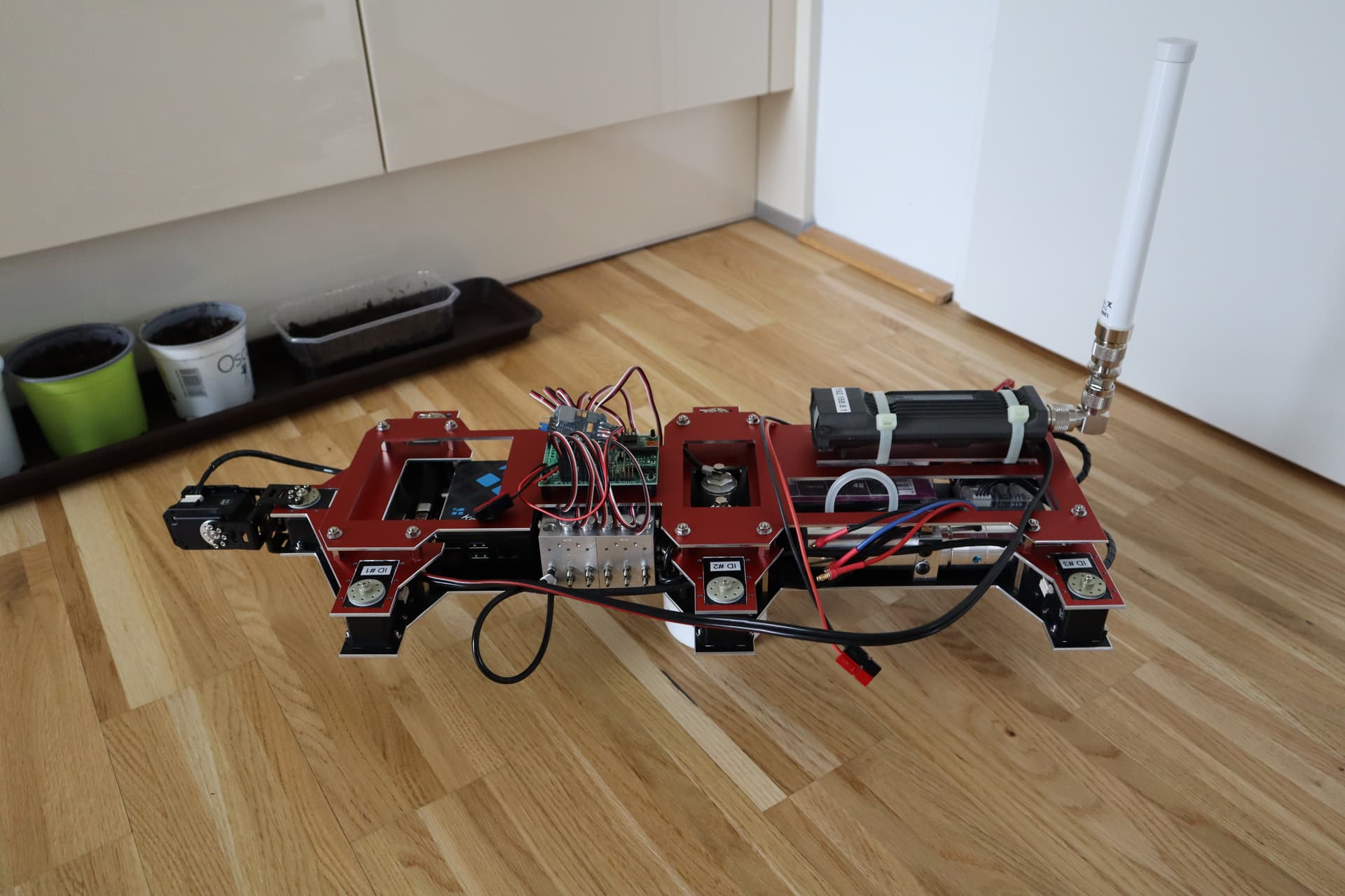
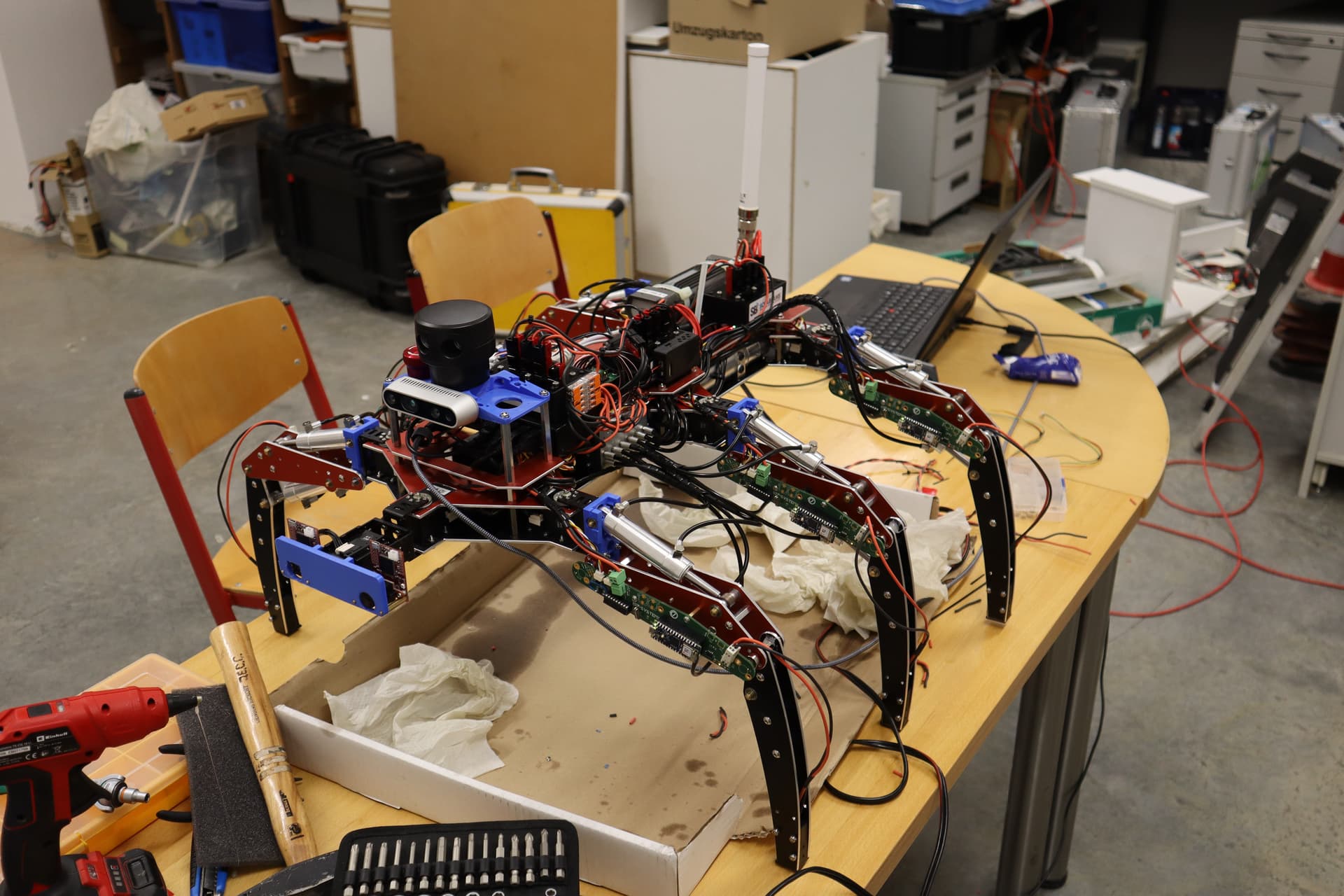
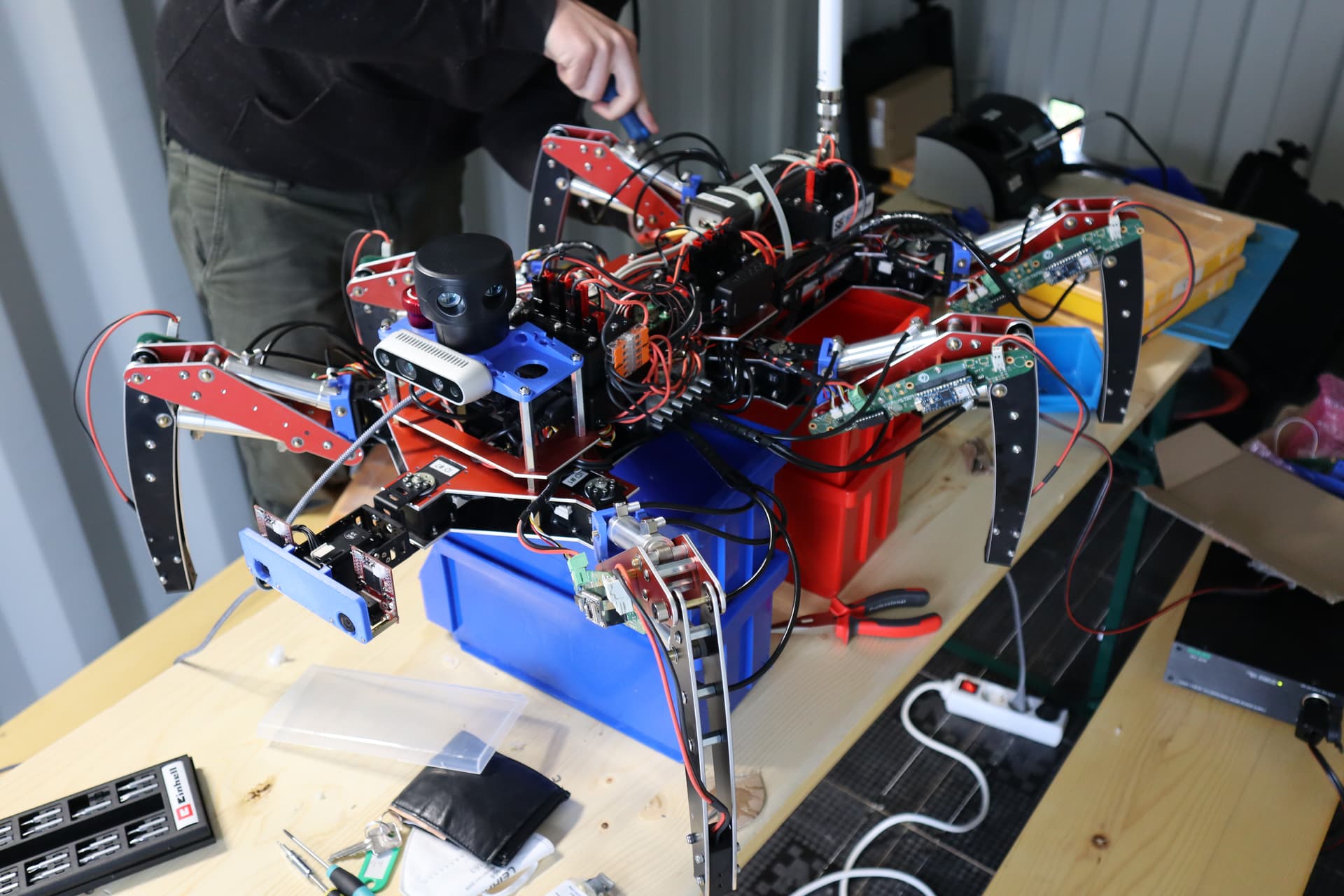
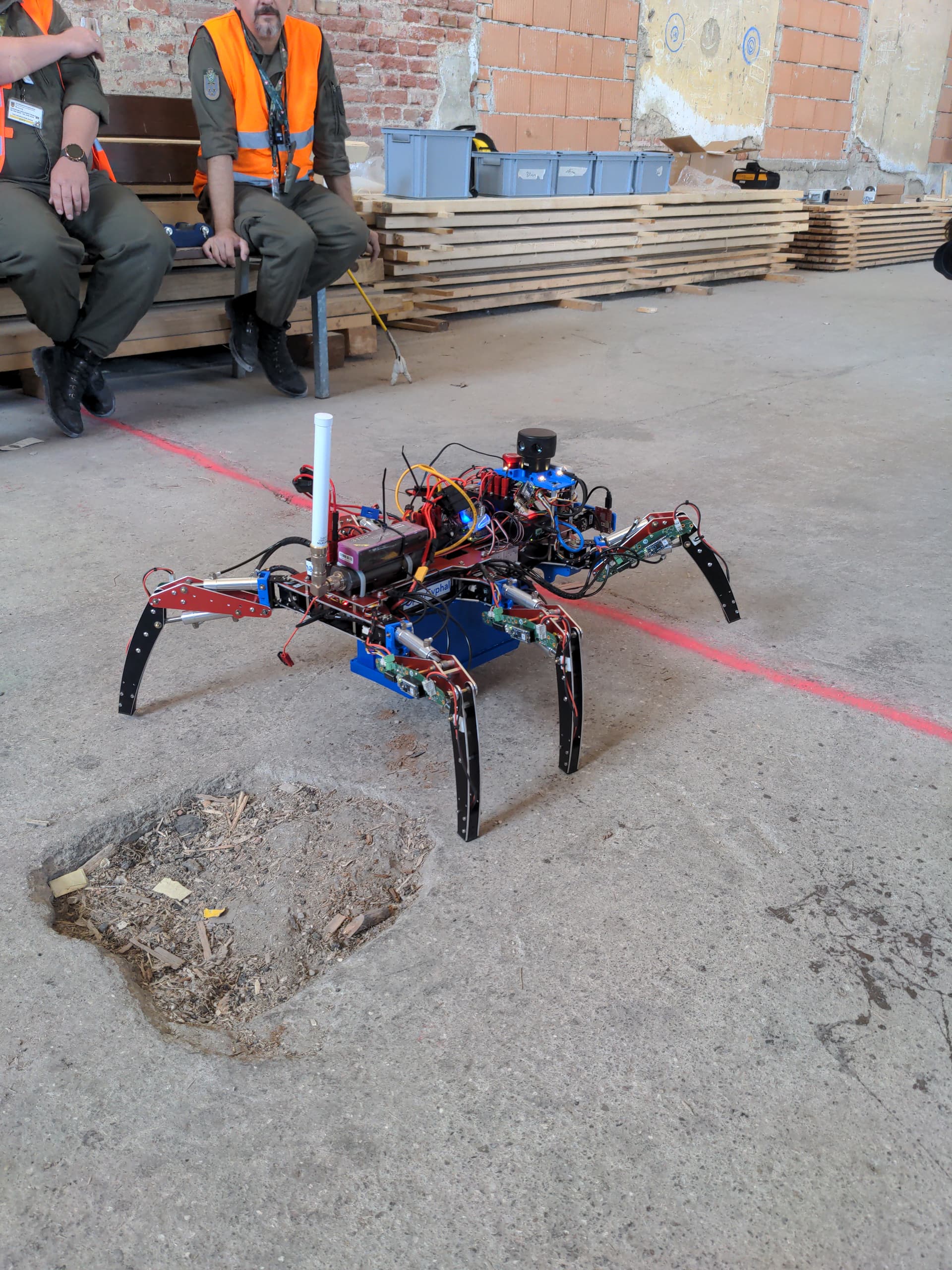
The next image shows the completely assembled hexapod robot. Both Realsense and 2D LIDAR (both are used for map building) can be seen on the forward sensor tower.

2022-05-23-L3X-Z-29

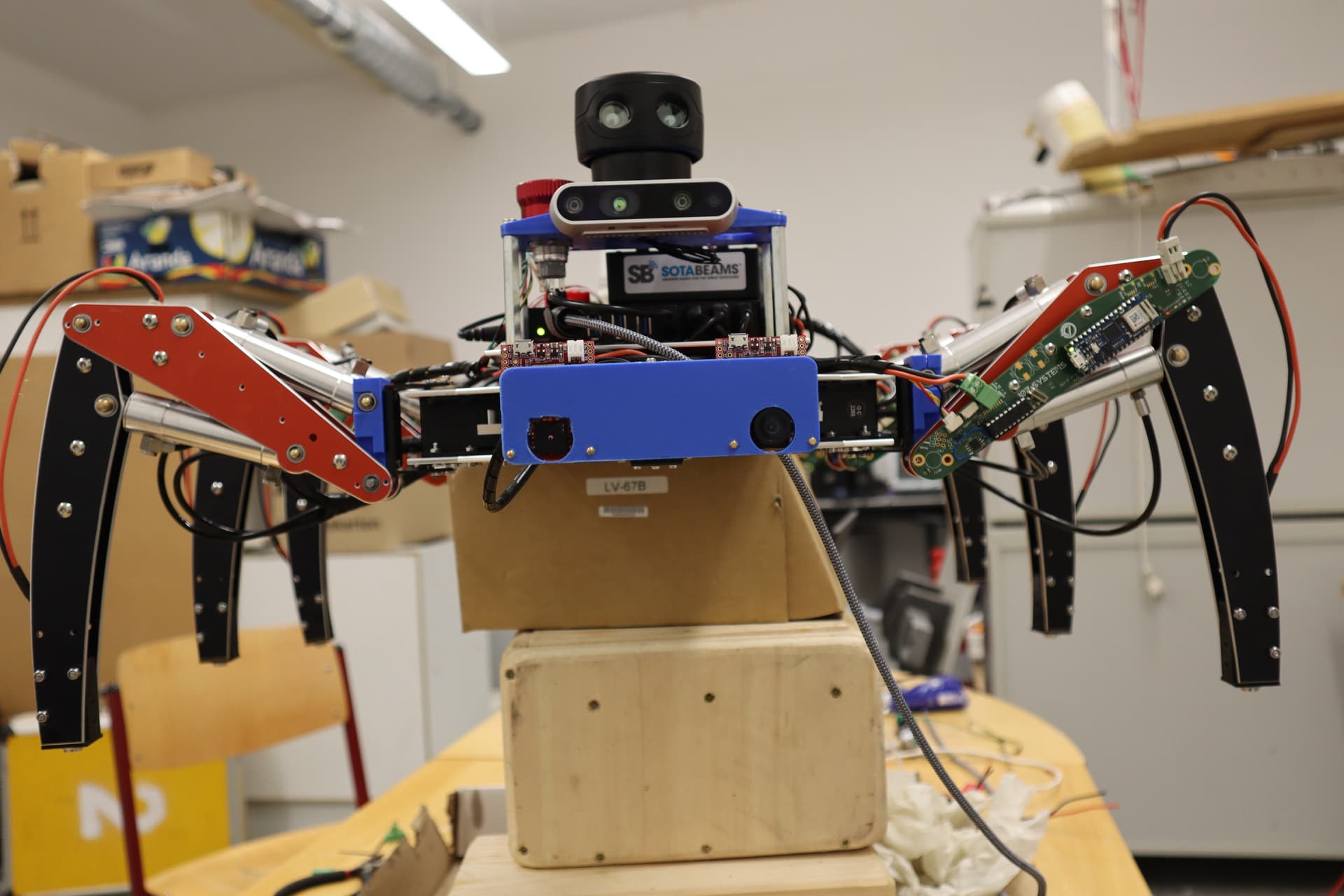
A side angle view at the assembled hexapod robot.

2022-05-23-L3X-Z-33

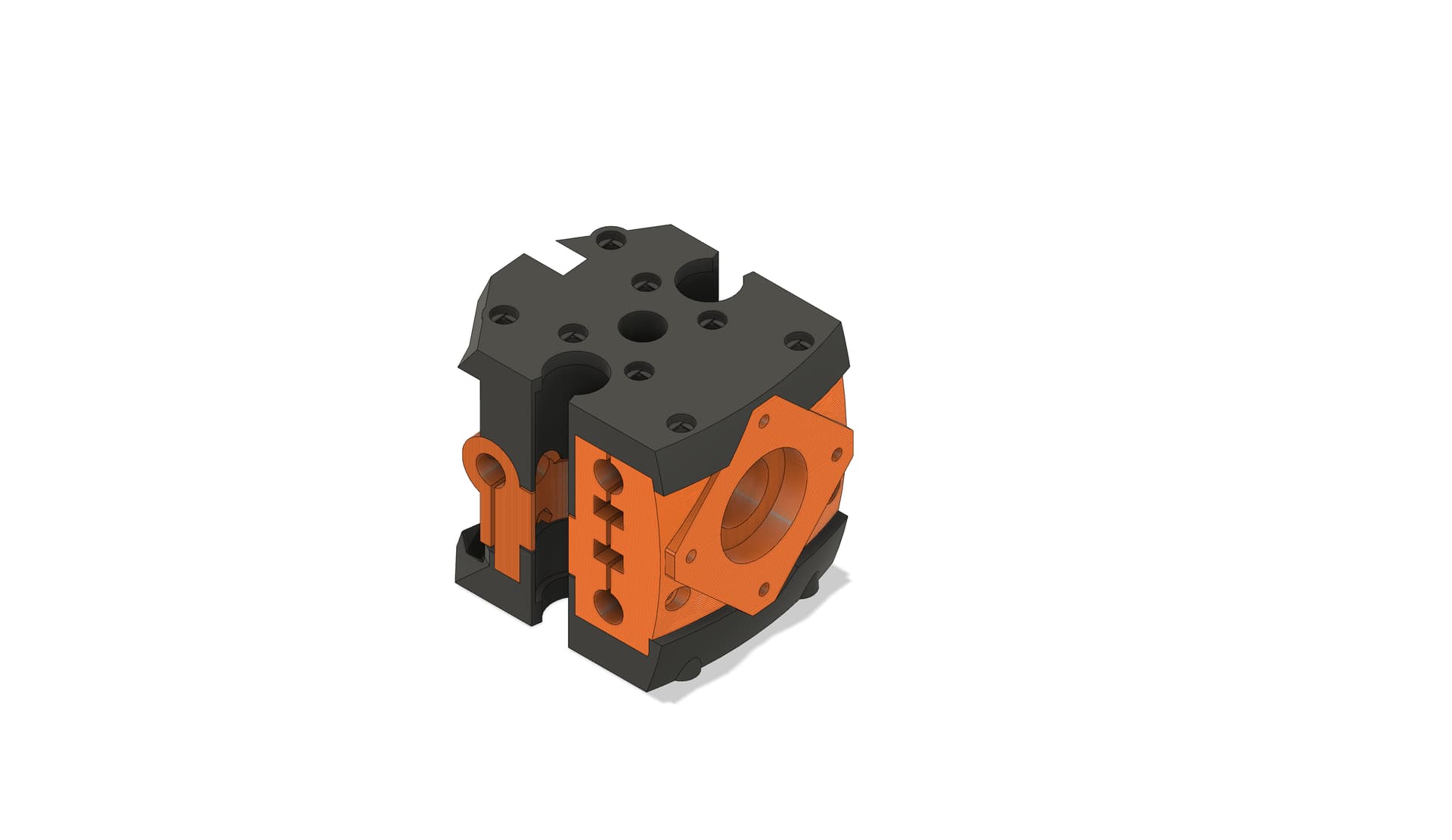
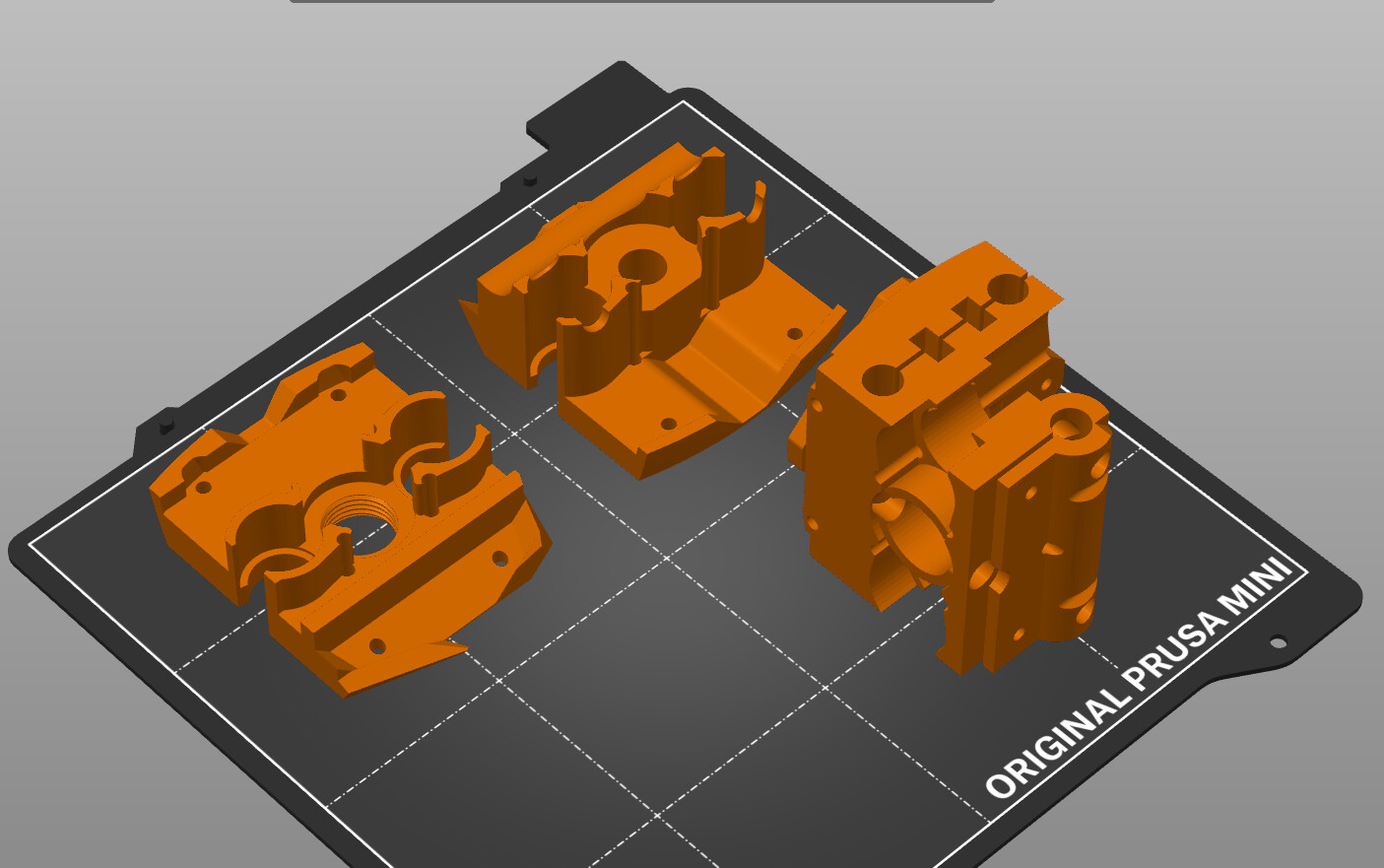
Unfortunately one of the 3D printed elements had a bit of an design issue leading to cracking of the 3D printed element when the hydraulic cylinders were fully extended:

2022-05-23-L3X-Z-31

This meant that we had to disassemble all legs and exchange the broken part with a freshly designed and printed one at the event itself.

2022-05-29-ELROB-2022-Alex-05

On this image all legs have been mounted again:

2022-05-29-ELROB-2022-Alex-11

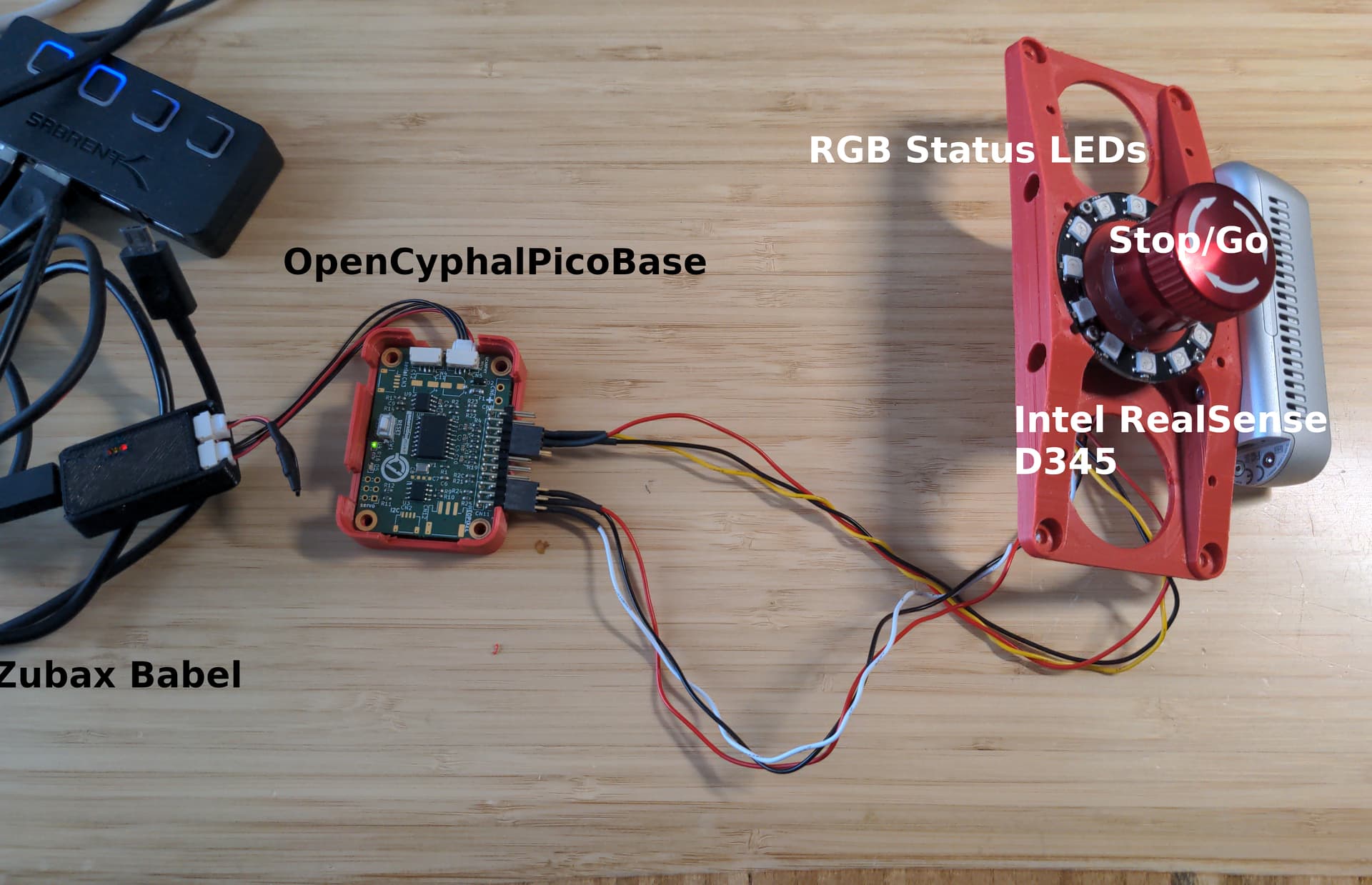
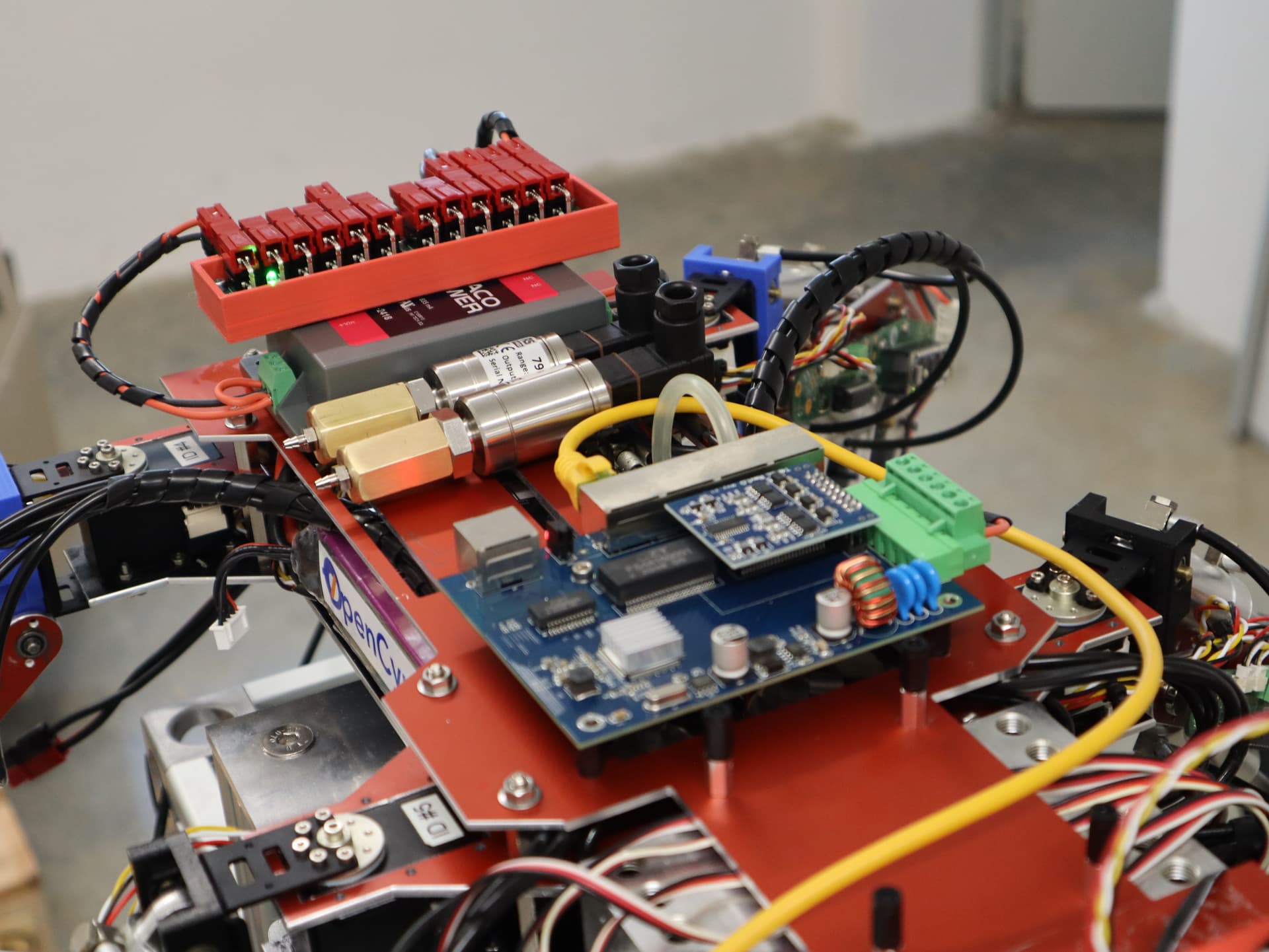
We also exchanged the sensor tower with a new version containing the required status LEDs for visualising the robot status to external (human) observers (Note the Neopixels):

2022-05-30-ELROB-2022-Alex-14

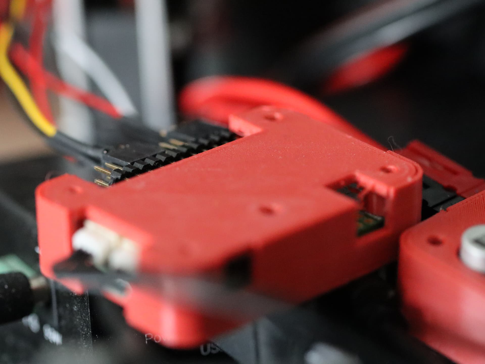
Those NeoPixel RGB LEDs are controlled via the so-called auxiliary controller which communicates with the main control software via OpenCyphal/CAN.

2022-05-30-ELROB-2022-Alex-13

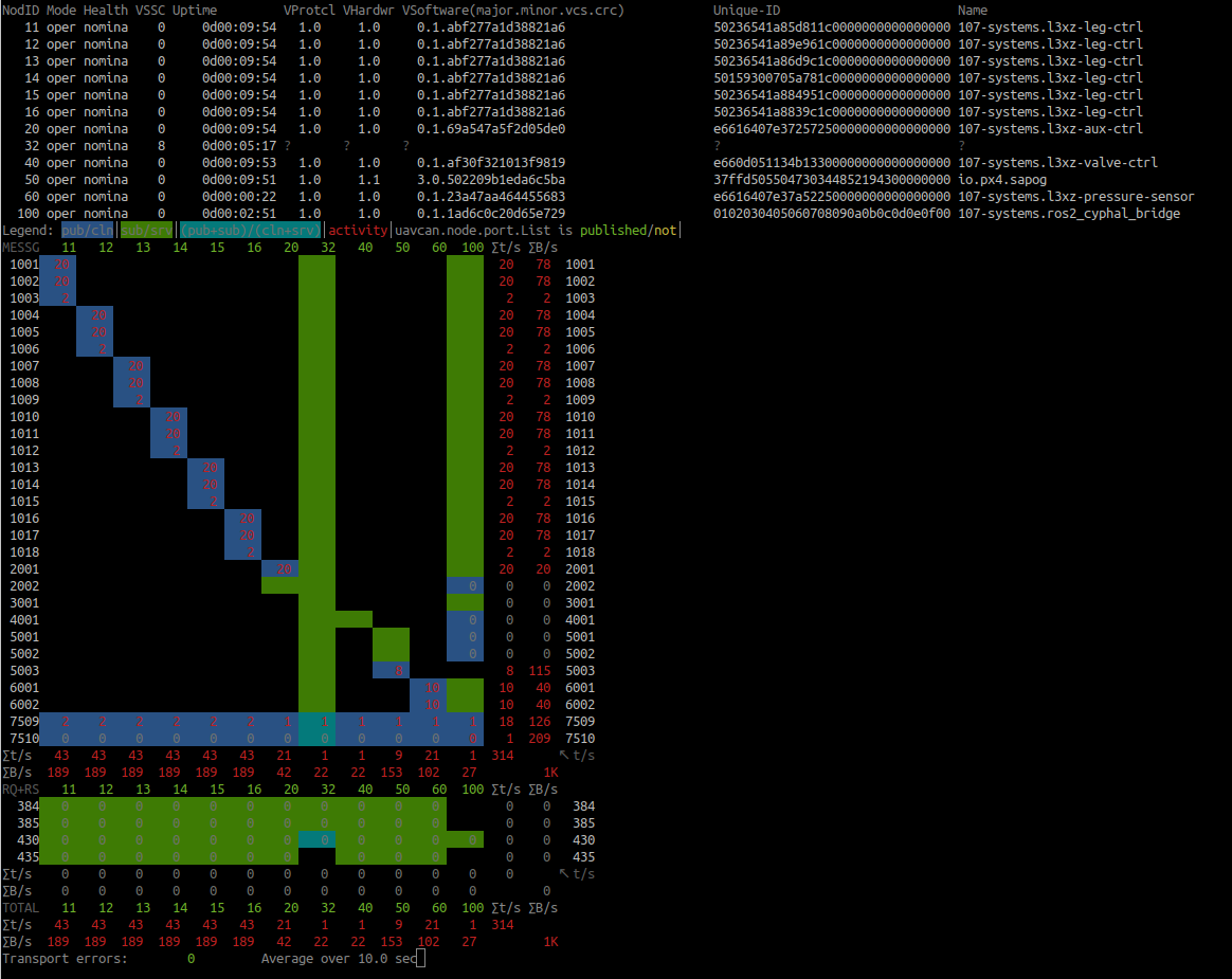
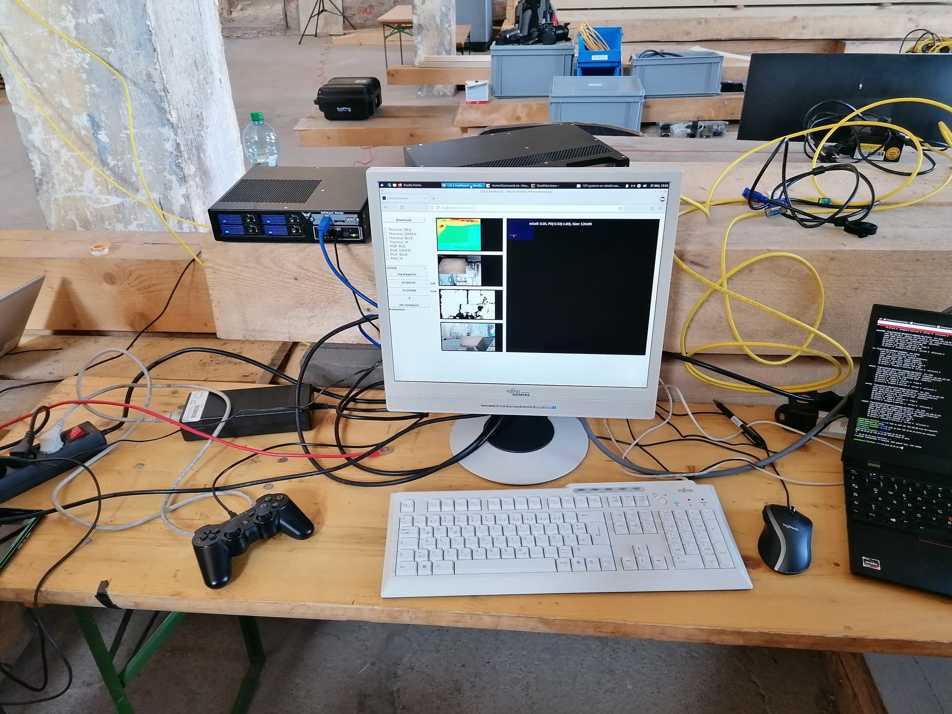
On the bottom of the robot there’s a radiation sensor mounted (firmware) which is another OpenCyphal/CAN connected node providing radiation sensing data to the robot control software (which streams this information via ROS topics to the operator station - shown below).

2022-05-31-ELROB-Jonas-05

The final image shows L3X-Z bravely doing the first step over the starting line during our run at the event:

2022-05-31-ELROB-2022-Alex-09

Ressources

All hardware design files, CAD design files and software are open-source and available within the 107-systems github organisation. There is a table within the main robots control software which might prove helpful if you are looking for a specific ressource.

Video

¹ @pavel.kirienko (Pavel Kirienko), @generationmake (Bernhard Mayer), @aentinger (Alexander Entinger), Jonas Wühr, Robert Hahn (OE3BHC)

4 Likes

Love it! Where did you get the hydraulic actuators? I’ve always wanted to play around with them.

Also, what’s the top forward speed of the robot?

1 Like

Here’s a tip for designing FFF parts, never apply a load that pulls at the bond between layers. That is, use the layered dimensions for compressive loads only. If you need to put parts in tension be sure you rely on the filament’s tensile strength not inter-layer adhesion. For example, I’m designing a part that has two axis that require tension. Instead of printing a solid part I’m designing three parts that snap together so I can print each in the proper orientation to avoid inter-layer tension.


The assembled part. All layering is in compression when assembled. (black is Poly-Carbonate and Orange is PET)


Note how the orientation of the different parts when printed (using FFF) are rotated so that the critical cylindrical volumes in each axis rely only on the filament tensile strength and not inter-layer adhesion.

1 Like

Thank you :blush: ! All hydraulic parts have been purchased from the :de: company Leimbach Modellbau.

Currently about 10 cm / second. The main limiting factor is the volume flow rate of the hydraulic pump which limits speed of the cylinder action. L3X-Z already contains a dual-pressure-circuit pump, enabling two separate hydraulic circuits in the robot, one for the left side, one for the right and therefore doubling the volume flow rate. Possible improvements would be:

  • Add another dual-pressure-circuit pump (doubling the volume flow rate).
  • Replace the current cylinders with cylinders with a smaller diameter (requiring less volume to be filled). (This is an option because the current cylinder diameter - and directly linked with it the applicable force - has been selected to be on the safe side, so there’s room for optimisation.

Unfortunately :de: made miniature hydraulic gear is :moneybag: (= expensive), so both options come with considerable cost. Any contribution (be it one-time or regular) would be greatly appreciated (shameless plug :wink:).

Thank you very much for your advice re FFF design. In this area there’s much I have to learn :bowing_man: . For example all those nice CNC-milled parts are from a ( :de: ) company which is in the business of producing front panels for electronic devices. They even have a self-developed, multi-platform software-tool tailored to creating such front panels where you can place your order directly from within the tool (talking about “industry 4.0” :wink: ). The cool thing about them is that per default they support panels up to 10 mm (more on request) so what I’ve been using them for is not for front panels but for custom CNC-milling. The not so cool part is that the import of DXF files (as cool as that feature is, since it allows you to feed the output from another CAD software into the tool) is not as straight-forward as it could be and requires some manual adjustment. Frankly, I’m incredibly happy that we did not have to rework a single part :wink: .

Love it! Looks very cool and neatly designed! Which CAD software have you used for this?

Thanks. I use Fusion 360 for my maker projects.

1 Like

It’s Friday :partying_face: . So following the tradition of IEEE Spectrum / Automaton let’s have a video friday :wink:

2 Likes

Since I’m a big fan of having neat logos representing the various projects I’m working on it was a given to have a nice logo for the hexapod project (possibly a bit late for this years ELROB but definitely in time for next years ENRICH). So let’s have it:

l3xz-logo-memento-mori

3 Likes

After taking more than six months since the culmination of ELROB 22, here it is at last: Everything you’ve ever (or maybe never) wanted to know about the L3X-Z construction and its participation in ELROB 22 is detailed in the following article:

3 Likes

I’d like to draw everyone’s attention to the growing amount of Cyphal-enabled boards in L3X-Z.

OpenCyphalPicoBase (Hardware, Firmware, Thread on OpenCyphal Forum)
This general purpose board is used for a variety of tasks such as auxiliary controller and radiation sensor.

OpenCyphalServoController12 (Hardware, Firmware)
This board allows to control up to 12 PWM RC servos via Cyphal. Within L3X-Z its used for controlling the hydraulic valves.

l3xz-leg-ctrl-hardware (Hardware, Firmware)
This board situated on each leg of L3X-Z determines the joints angular position with magnetic position sensors and publishes it using Cyphal to various consumers.

CAN-Power-Injector (Hardware)
No Cyphal board but allows to inject 5V (and up to 5A) into the CAN bus supplying all connected devices. No more separate wires for power supply needed.

CC @generationmake

3 Likes

This is neat. Would be even neater if the firmware did not have hard-coded port identifiers and did not rely on the node-IDs for application-layer functionality! I take it that with the new 107-Arduino-Cyphal it would be a no-brainer to drop the hard-coded topics.

Its happening :wink: main blocker was persistent register storage which is now solved. Expect a separate post in the 107-Arduino-Cyphal thread and on the subject of 107-Arduino-Cyphal-Support.

2 Likes

A fully Cyphal-conforming firmware for the auxiliary controller is now complete (incl. configurable port IDs, persistent register storage, etc.).

The hardware is based on the (much mentioned) OpenCyphalPicoBase.

Its features are robot status visualization via RGB LEDs (as mandated by the ELROB rules) and publishing of the status of the Stop/Go button.

Here’s how the led colour can be changed via publishing to the configured port ID using yakut (cyphal.sub.light_mode.id = 2002, 1 = RED):

y pub -N1 2002:uavcan.primitive.scalar.Integer8.1.0 1

Below a video of my cycling through the availale colours by publishing the appropriate values via yakut:

CC @generationmake

3 Likes

love it!

2 Likes

Another milestone has been achieve. The full Cyphal network has been wired up (on a yet temporary basis) and all nodes have been configured using yakut and yaml. (Details to be found here).

Afterwards I was rewarded by seeing the full transport matrix and all 6 leg controllers, 1 auxiliary controller, 1 valve controller as well as one Orel 20 (for the hydraulic pump). The radiation sensor is not in the list as its currently under final assembly @generationmake .

Here’s a couple of more images from the setup:

1 x Auxiliary Controller

6 x Leg Controller

1 x Valve Controller

1 x CAN Power Injector

3 Likes

Very nova!

1 Like

With the ENRICH 2023 coming closer and closer its time for L3X-Z to assume its final Gestalt :wink:

Here are a couple of impressions from the latest building session:

RS485-Power-Injector and CAN-Power-Injector located at the front of the L3X-Z:

A close-up picture of the servo-actuated hydraulic valve blocks:

The newly designed “Dragonbeard” (thank you very much @scottdixon for your FANTASTIC work !!! :exploding_head: :bowing_man: ) colour/thermal imaging head which has both pan and tilt control:

Ressources:

A close-up picture of the thermal camera:

An impression along the longitudinal axis of the robot:

Isometric view:

A OpenCyphalPicoBase running the auxiliary controller firmware:

(Naked) 4-Port PoE Switch, DC/DC-Converter for PoE Upconversion (4S LiFePo → 48 VDC), Power Distributor, hydraulic pressure sensors:

The (more or less) final beast:

Please enjoy :bowing_man:

4 Likes

Cool stuff. Keep it coming.

I just wanna post this: Neural Volumetric Memory for Visual Locomotion Control

Maybe it’ll be relevant at some point in the future.

1 Like

2 Likes

Logged :grin: much to explore, we have barely scratched the surface :grin: .

1 Like

With ENRICH 2023 very soon upon us (less than two weeks) it’s about time for L3X-Z to come together :wink: .

On the image below you can see the hexapods nearly complete Cyphal network:

are 9 (10) 107-Arduino-Cyphal powered devices that run without a hiccup on L3X-Z’s internal network!

:partying_face: :rocket: :partying_face: :rocket: :partying_face: :rocket: :partying_face: :rocket: :partying_face:

Additionally there’s a Orel 20 ESC for driving the hydraulic pump as well as the ros2_cyphal_bridge for streaming selected Cyphal messages as ROS topics for further internal processing.

This brings the total number of Cyphal network devices up to 11 (12).

Let’s close with some robot image spam :grin:

3 Likes