Hardware example using UAVCAN v1 on Arduino

The 107-Arduino-UAVCAN library is now at a point where it can be used to make small working projects and here is an example how to do it.

This example uses unregulated Subject-IDs. Register API is not yet implemented in the library so the Subject-IDs are coded in the Arduino sketch. The example generates a Heartbeat message every second.

My example uses an Arduino MKR WiFi 1010 with a MKR CAN Shield.

The Arduino has a builtin LED and two more LEDs are connected to pin 2 and 5. A tactile switch is connected to pin 4. Here is a photo:

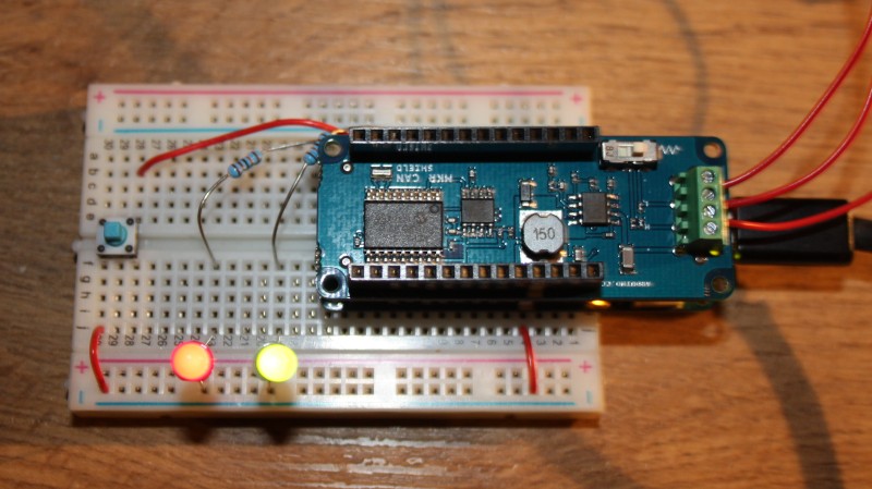
At the moment the library only supports the uavcan.primitive.scalar.Bit.1.0. The Arduino sketch subscribes to three Subject-IDs 1620, 1621 and 1622. Publishing to these Subject-IDs turns the LEDs on the Arduino on and off.

This can be done using pyuavcan-cli.

switch LED on with

yakut -i 'CAN(can.media.socketcan.SocketCANMedia("can0",8),59)' pub 1620.uavcan.primitive.scalar.Bit.1.0 'value: true'

switch LED off with

yakut -i 'CAN(can.media.socketcan.SocketCANMedia("can0",8),59)' pub 1620.uavcan.primitive.scalar.Bit.1.0 'value: false'

use Subject-ID 1621 and 1622 for the other LEDs.

The example also publishes to two other Subject-IDs: 1623 and 1624
Subject-ID 1623 is published every second and the value is toggled every second.
Subject-ID 1624 is connected to the switch at pin 4 and is transmitted every time the state of the switch changes.

These messages can also be received using pyuavcan:

yakut -i 'CAN(can.media.socketcan.SocketCANMedia("can0",8),59)' sub 1624.uavcan.primitive.scalar.Bit.1.0

The output should be like:

---
1624:
  _metadata_:
    timestamp:
      system: 1609452862.629312
      monotonic: 34714.947701
    priority: nominal
    transfer_id: 1
    source_node_id: 13
  value: false

---
1624:
  _metadata_:
    timestamp:
      system: 1609452866.743069
      monotonic: 34719.061459
    priority: nominal
    transfer_id: 2
    source_node_id: 13
  value: true


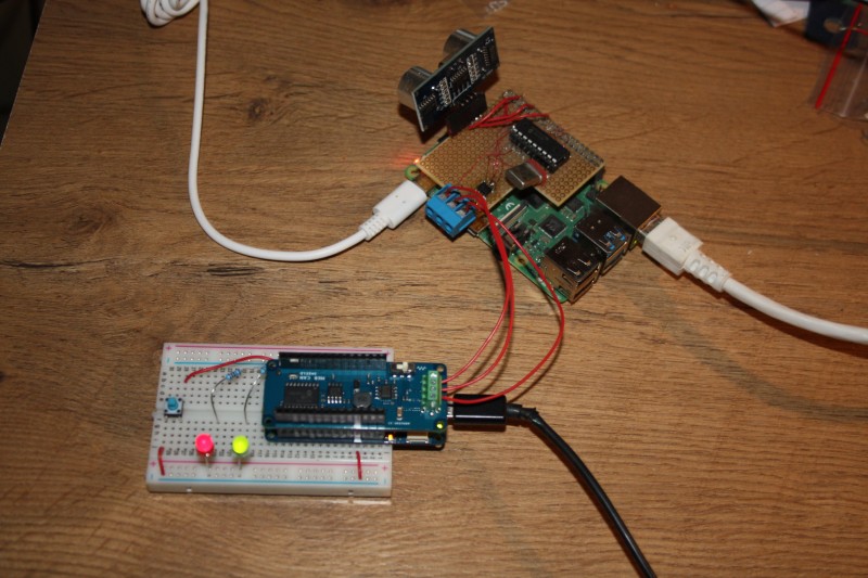
In my test setup pyuavcan is running on a Raspberry Pi. It is connected to the CAN bus using a MCP2515. Here is a photo of the setup:

Here is the full source code of the sketch:

/*
 * This example creates a UAVCAN node. The builtin LED can be switched on and off using UAVCAN.
 * It also shows periodic transmission of a UAVCAN heartbeat message via CAN.
 *
 * switch built in LED on with
 *   pyuavcan pub 1620.uavcan.primitive.scalar.Bit.1.0 'value: true' --tr='CAN(can.media.socketcan.SocketCANMedia("can0",8),59)'
 *
 * switch built in LED off with
 *   pyuavcan pub 1620.uavcan.primitive.scalar.Bit.1.0 'value: false' --tr='CAN(can.media.socketcan.SocketCANMedia("can0",8),59)'
 *
 * Hardware:
 *   - Arduino MKR family board, e.g. MKR VIDOR 4000
 *   - Arduino MKR CAN shield
 */

/**************************************************************************************
 * INCLUDE
 **************************************************************************************/

#include <SPI.h>

#include <ArduinoUAVCAN.h>
#include <ArduinoMCP2515.h>

/**************************************************************************************
 * DEFINES
 **************************************************************************************/

#define LED1 2
#define LED2 5
#define SWITCH 4

/**************************************************************************************
 * CONSTANTS
 **************************************************************************************/

static int const MKRCAN_MCP2515_CS_PIN  = 3;
static int const MKRCAN_MCP2515_INT_PIN = 7;
static CanardPortID const BIT_PORT_ID   = 1620U;
static CanardPortID const BIT_PORT_ID1   = 1621U;
static CanardPortID const BIT_PORT_ID2   = 1622U;
static CanardPortID const BIT_PORT_ID3   = 1623U;
static CanardPortID const BIT_PORT_ID4   = 1624U;

/**************************************************************************************
 * FUNCTION DECLARATION
 **************************************************************************************/

void    spi_select        ();
void    spi_deselect       ();
uint8_t spi_transfer       (uint8_t const);
void    onExternalEvent    ();
bool    transmitCanFrame   (CanardFrame const &);
void    onReceiveBufferFull(CanardFrame const &);
void    onBit_1_0_Received (CanardTransfer const &, ArduinoUAVCAN &);
void    onBit_1_0_Received1 (CanardTransfer const &, ArduinoUAVCAN &);
void    onBit_1_0_Received2 (CanardTransfer const &, ArduinoUAVCAN &);

/**************************************************************************************
 * GLOBAL VARIABLES
 **************************************************************************************/

ArduinoMCP2515 mcp2515(spi_select,
                       spi_deselect,
                       spi_transfer,
                       micros,
                       onReceiveBufferFull,
                       nullptr);

ArduinoUAVCAN uavcan(13, transmitCanFrame);

Heartbeat_1_0 hb;
Bit_1_0<BIT_PORT_ID3> uavcan_bit3;
Bit_1_0<BIT_PORT_ID4> uavcan_bit4;

/**************************************************************************************
 * SETUP/LOOP
 **************************************************************************************/

void setup()
{
  Serial.begin(9600);
  while(!Serial) { }

  /* Setup LED and initialize */
  pinMode(LED_BUILTIN, OUTPUT);
  digitalWrite(LED_BUILTIN, LOW);
  pinMode(LED1, OUTPUT);
  digitalWrite(LED1, LOW);
  pinMode(LED2, OUTPUT);
  digitalWrite(LED2, LOW);
  pinMode(SWITCH, INPUT_PULLUP);

  /* Setup SPI access */
  SPI.begin();
  pinMode(MKRCAN_MCP2515_CS_PIN, OUTPUT);
  digitalWrite(MKRCAN_MCP2515_CS_PIN, HIGH);

  /* Attach interrupt handler to register MCP2515 signaled by taking INT low */
  pinMode(MKRCAN_MCP2515_INT_PIN, INPUT_PULLUP);
  attachInterrupt(digitalPinToInterrupt(MKRCAN_MCP2515_INT_PIN), onExternalEvent, FALLING);

  /* Initialize MCP2515 */
  mcp2515.begin();
  mcp2515.setBitRate(CanBitRate::BR_250kBPS);
  mcp2515.setNormalMode();

  /* Configure initial bit */
  uavcan_bit3.data.value = false;
  uavcan_bit4.data.value = false;
  /* Configure initial heartbeat */
  hb.data.uptime = 0;
  hb = Heartbeat_1_0::Health::NOMINAL;
  hb = Heartbeat_1_0::Mode::INITIALIZATION;
  hb.data.vendor_specific_status_code = 0;

  /* Subscribe to the reception of Bit message. */
  uavcan.subscribe<Bit_1_0<BIT_PORT_ID>>(onBit_1_0_Received);
  uavcan.subscribe<Bit_1_0<BIT_PORT_ID1>>(onBit_1_0_Received1);
  uavcan.subscribe<Bit_1_0<BIT_PORT_ID2>>(onBit_1_0_Received2);
  Serial.println("init finished");
}

void loop()
{
  static bool a=0;
  bool b;
  b=digitalRead(SWITCH);
  if(a!=b)
  {
    uavcan_bit4.data.value = b;
    uavcan.publish(uavcan_bit4);   
    Serial.print("send bit: ");
    Serial.println(b); 
  }
  a=b;
  
  /* Update the heartbeat object */
  hb.data.uptime = millis() / 1000;
  hb = Heartbeat_1_0::Mode::OPERATIONAL;

  /* Publish the heartbeat once/second */
  static unsigned long prev = 0;
  unsigned long const now = millis();
  if(now - prev > 1000) {
    if(uavcan_bit3.data.value==true) uavcan_bit3.data.value=false;
    else uavcan_bit3.data.value=true;
    uavcan.publish(uavcan_bit3);
    uavcan.publish(hb);
    prev = now;
  }

  /* Transmit all enqeued CAN frames */
  while(uavcan.transmitCanFrame()) { }
}

/**************************************************************************************
 * FUNCTION DEFINITION
 **************************************************************************************/

void spi_select()
{
  digitalWrite(MKRCAN_MCP2515_CS_PIN, LOW);
}

void spi_deselect()
{
  digitalWrite(MKRCAN_MCP2515_CS_PIN, HIGH);
}

uint8_t spi_transfer(uint8_t const data)
{
  return SPI.transfer(data);
}

void onExternalEvent()
{
  mcp2515.onExternalEventHandler();
}

bool transmitCanFrame(CanardFrame const & frame)
{
  return mcp2515.transmit(frame);
}

void onReceiveBufferFull(CanardFrame const & frame)
{
  uavcan.onCanFrameReceived(frame);
}

void onBit_1_0_Received(CanardTransfer const & transfer, ArduinoUAVCAN & /* uavcan */)
{
  Bit_1_0<BIT_PORT_ID> const uavcan_led = Bit_1_0<BIT_PORT_ID>::deserialize(transfer);

  if(uavcan_led.data.value)
  {
    digitalWrite(LED_BUILTIN, HIGH);
    Serial.println("Received Bit0: true");
  }
  else
  {
    digitalWrite(LED_BUILTIN, LOW);
    Serial.println("Received Bit0: false");
  }
}
void onBit_1_0_Received1(CanardTransfer const & transfer, ArduinoUAVCAN & /* uavcan */)
{
  Bit_1_0<BIT_PORT_ID1> const uavcan_led1 = Bit_1_0<BIT_PORT_ID1>::deserialize(transfer);

  if(uavcan_led1.data.value)
  {
    digitalWrite(LED1, HIGH);
    Serial.println("Received Bit1: true");
  }
  else
  {
    digitalWrite(LED1, LOW);
    Serial.println("Received Bit1: false");
  }
}
void onBit_1_0_Received2(CanardTransfer const & transfer, ArduinoUAVCAN & /* uavcan */)
{
  Bit_1_0<BIT_PORT_ID2> const uavcan_led2 = Bit_1_0<BIT_PORT_ID2>::deserialize(transfer);

  if(uavcan_led2.data.value)
  {
    digitalWrite(LED2, HIGH);
    Serial.println("Received Bit2: true");
  }
  else
  {
    digitalWrite(LED2, LOW);
    Serial.println("Received Bit2: false");
  }
}
2 Likes

I edited the previous post and replaced pyuavcan commands with yakut commands.

2 Likes

Now that the 107-Arduino-UAVCAN library officially supports different datatypes this example needed to be updated.

From the hardware perspective I switched to a Arduino Nano 33 IoT. This board is very similar to the previous used Arduino MKR WiFi 1010 but lacks the LiPo charger and is a little bit cheaper. I placed the Arduino on a stripboard and added a Microchip MCP2515 CAN controller and a CAN driver. The board is solely powered by the CAN bus using the Dronecode connector. Additionally there are three LEDs and a switch and a potentiometer connected to the analog in of the Arduino. Finally there is a Maxim DS18B20 temperature sensor on the board.

The sketch uses different subject ids as shown in the following table:

Subject-ID - direction - primitive - description
1620       - sub       - Bit       - LED0 (yellow)
1621       - sub       - Bit       - LED1 (red)
1622       - sub       - Bit       - LED2 (green)
1623       - pub       - Bit       - SWITCH
1624       - pub       - Bit       - TOGGLE
1630       - pub       - Real32    - Temperature
1640       - pub       - Real32    - Analog
1641       - sub       - Real32    - LED_PWM (yellow)

At the moment the library doesn’t support changing these subject ids so they are hard coded.

The bit inputs directly control the LEDs and turn them on and off. Every time the state of the switch changes a message is transmitted an subject id 1623. The subject id 1624 is transmitted every second and the state toggles. The value of the temperature sensor is transmitted every second as Real32 on subject id 1630, the value of the analog sensor on 1640. There is a Real32 input on subject id 1641 which controls the brightness of the yellow led.

This is the source code of the sketch:

/*
 * This example creates a UAVCAN node. The builtin LED can be switched on and off using UAVCAN.
 * It also shows periodic transmission of a UAVCAN heartbeat message via CAN.
 *
 * switch built in LED on with
 *   pyuavcan pub 1620.uavcan.primitive.scalar.Bit.1.0 'value: true' --tr='CAN(can.media.socketcan.SocketCANMedia("can0",8),59)'
 *
 * switch built in LED off with
 *   pyuavcan pub 1620.uavcan.primitive.scalar.Bit.1.0 'value: false' --tr='CAN(can.media.socketcan.SocketCANMedia("can0",8),59)'
 *
 * Hardware:
 *   - Arduino MKR family board, e.g. MKR VIDOR 4000
 *   - Arduino MKR CAN shield
 *   or
 *   - Arduino Nano 33 IoT
 *   - MCP2515
 *   
 * Used Subject-IDs
 * 1620 - sub - Bit    - LED0 (yellow)
 * 1621 - sub - Bit    - LED1 (red)
 * 1622 - sub - Bit    - LED2 (green)
 * 1623 - pub - Bit    - SWITCH
 * 1624 - pub - Bit    - TOGGLE
 * 1630 - pub - Real32 - Temperature
 * 1640 - pub - Real32 - Analog
 * 1641 - sub - Real32 - LED_PWM (yellow)
 */

/**************************************************************************************
 * INCLUDE
 **************************************************************************************/

#include <SPI.h>

#include <ArduinoUAVCAN.h>
#include <ArduinoMCP2515.h>
#include <OneWire.h>
#include <DallasTemperature.h>

/**************************************************************************************
 * DEFINES
 **************************************************************************************/

#define LED1 2
#define LED2 5
#define LED_PWM 6
#define SWITCH 4
#define ANALOG_PIN A0

#define ONE_WIRE_BUS 7

/**************************************************************************************
 * NAMESPACE
 **************************************************************************************/

using namespace uavcan::primitive::scalar;

/**************************************************************************************
 * CONSTANTS
 **************************************************************************************/

static int const MKRCAN_MCP2515_CS_PIN  = 3;
static int const MKRCAN_MCP2515_INT_PIN = 9;
static CanardPortID const ID_LED0        = 1620U;
static CanardPortID const ID_LED1        = 1621U;
static CanardPortID const ID_LED2        = 1622U;
static CanardPortID const ID_SWITCH      = 1623U;
static CanardPortID const ID_TOGGLE      = 1624U;
static CanardPortID const ID_TEMPERATURE = 1630U;
static CanardPortID const ID_ANALOG      = 1640U;
static CanardPortID const ID_LED_PWM     = 1641U;

/**************************************************************************************
 * FUNCTION DECLARATION
 **************************************************************************************/

void    spi_select        ();
void    spi_deselect       ();
uint8_t spi_transfer       (uint8_t const);
void    onExternalEvent    ();
bool    transmitCanFrame   (CanardFrame const &);
void    onReceiveBufferFull(CanardFrame const &);
void    onLed0_Received (CanardTransfer const &, ArduinoUAVCAN &);
void    onLed1_Received (CanardTransfer const &, ArduinoUAVCAN &);
void    onLed2_Received (CanardTransfer const &, ArduinoUAVCAN &);
void    onLed_pwm_Received (CanardTransfer const &, ArduinoUAVCAN &);

/**************************************************************************************
 * GLOBAL VARIABLES
 **************************************************************************************/

ArduinoMCP2515 mcp2515(spi_select,
                       spi_deselect,
                       spi_transfer,
                       micros,
                       onReceiveBufferFull,
                       nullptr);

ArduinoUAVCAN uc(15, transmitCanFrame);

Heartbeat_1_0 hb;
Bit_1_0<ID_SWITCH> uavcan_switch;
Bit_1_0<ID_TOGGLE> uavcan_toggle;
Real32_1_0<ID_ANALOG> uavcan_analog;
Real32_1_0<ID_TEMPERATURE> uavcan_temperature;

/* setup one wire and temperature sensors */
OneWire oneWire(ONE_WIRE_BUS);
DallasTemperature sensors(&oneWire);

/**************************************************************************************
 * SETUP/LOOP
 **************************************************************************************/

void setup()
{
  Serial.begin(9600);
//  while(!Serial) { }

  /* Setup LED pins and initialize */
  pinMode(LED_PWM, OUTPUT);
  digitalWrite(LED_PWM, LOW);
  pinMode(LED1, OUTPUT);
  digitalWrite(LED1, LOW);
  pinMode(LED2, OUTPUT);
  digitalWrite(LED2, LOW);
  pinMode(SWITCH, INPUT_PULLUP);

  /* Setup SPI access */
  SPI.begin();
  pinMode(MKRCAN_MCP2515_CS_PIN, OUTPUT);
  digitalWrite(MKRCAN_MCP2515_CS_PIN, HIGH);

  /* Attach interrupt handler to register MCP2515 signaled by taking INT low */
  pinMode(MKRCAN_MCP2515_INT_PIN, INPUT_PULLUP);
  attachInterrupt(digitalPinToInterrupt(MKRCAN_MCP2515_INT_PIN), onExternalEvent, FALLING);

  /* Initialize MCP2515 */
  mcp2515.begin();
  mcp2515.setBitRate(CanBitRate::BR_250kBPS_16MHZ);
  mcp2515.setNormalMode();

  /* Configure initial values */
  uavcan_switch.data.value = false;
  uavcan_toggle.data.value = false;
  uavcan_analog.data.value = 0.0;
  uavcan_temperature.data.value = 0.0;
  /* Configure initial heartbeat */
  hb.data.uptime = 0;
  hb = Heartbeat_1_0::Health::NOMINAL;
  hb = Heartbeat_1_0::Mode::INITIALIZATION;
  hb.data.vendor_specific_status_code = 0;

  /* Subscribe to the reception of Bit message. */
  uc.subscribe<Bit_1_0<ID_LED0>>(onLed0_Received);
  uc.subscribe<Bit_1_0<ID_LED1>>(onLed1_Received);
  uc.subscribe<Bit_1_0<ID_LED2>>(onLed2_Received);
  uc.subscribe<Real32_1_0<ID_LED_PWM>>(onLed_pwm_Received);
  Serial.println("init finished");

  /* init and check temperature sensors */
  Serial.print("Locating devices...");
  sensors.begin();
  Serial.print("Found ");
  Serial.print(sensors.getDeviceCount(), DEC);
  Serial.println(" devices.");
}

void loop()
{
  /* check switch */
  static bool switch_old=0;
  bool switch_in;
  switch_in=digitalRead(SWITCH);
  if(switch_old!=switch_in)
  {
    uavcan_switch.data.value = switch_in;
    uc.publish(uavcan_switch);   
    Serial.print("send bit: ");
    Serial.println(switch_in); 
  }
  switch_old=switch_in;
  
  /* Update the heartbeat object */
  hb.data.uptime = millis() / 1000;
  hb = Heartbeat_1_0::Mode::OPERATIONAL;

  /* Publish the heartbeat once/second */
  static unsigned long prev = 0;
  unsigned long const now = millis();
  if(now - prev > 1000) {
  /* toggle bit */
    if(uavcan_toggle.data.value==true) uavcan_toggle.data.value=false;
    else uavcan_toggle.data.value=true;
    uc.publish(uavcan_toggle);
    uc.publish(hb);

  /* read temperature value */
    Serial.print("Requesting temperatures...");
    sensors.requestTemperatures(); // Send the command to get temperatures
    Serial.println("DONE");
    float tempC = sensors.getTempCByIndex(0);
  
    if(tempC != DEVICE_DISCONNECTED_C) 
    {
      Serial.print("Temperature for the device 1 (index 0) is: ");
      Serial.println(tempC);
      uavcan_temperature.data.value = tempC;
      uc.publish(uavcan_temperature);   
    } 
    else
    {
      Serial.println("Error: Could not read temperature data");
    }

  /* read analog value */
    float analog=analogRead(ANALOG_PIN)/1023.0;
    Serial.print("Analog Pin: ");
    Serial.println(analog);
    uavcan_analog.data.value = analog;
    uc.publish(uavcan_analog);   

    prev = now;
  }

  /* Transmit all enqeued CAN frames */
  while(uc.transmitCanFrame()) { }
}

/**************************************************************************************
 * FUNCTION DEFINITION
 **************************************************************************************/

void spi_select()
{
  digitalWrite(MKRCAN_MCP2515_CS_PIN, LOW);
}

void spi_deselect()
{
  digitalWrite(MKRCAN_MCP2515_CS_PIN, HIGH);
}

uint8_t spi_transfer(uint8_t const data)
{
  return SPI.transfer(data);
}

void onExternalEvent()
{
  mcp2515.onExternalEventHandler();
}

bool transmitCanFrame(CanardFrame const & frame)
{
  return mcp2515.transmit(frame);
}

void onReceiveBufferFull(CanardFrame const & frame)
{
  uc.onCanFrameReceived(frame);
}

void onLed0_Received(CanardTransfer const & transfer, ArduinoUAVCAN & /* uavcan */)
{
  Bit_1_0<ID_LED0> const uavcan_led = Bit_1_0<ID_LED0>::deserialize(transfer);

  if(uavcan_led.data.value)
  {
    digitalWrite(LED_PWM, HIGH);
    Serial.println("Received Bit0: true");
  }
  else
  {
    digitalWrite(LED_PWM, LOW);
    Serial.println("Received Bit0: false");
  }
}
void onLed1_Received(CanardTransfer const & transfer, ArduinoUAVCAN & /* uavcan */)
{
  Bit_1_0<ID_LED1> const uavcan_led1 = Bit_1_0<ID_LED1>::deserialize(transfer);

  if(uavcan_led1.data.value)
  {
    digitalWrite(LED1, HIGH);
    Serial.println("Received Bit1: true");
  }
  else
  {
    digitalWrite(LED1, LOW);
    Serial.println("Received Bit1: false");
  }
}
void onLed2_Received(CanardTransfer const & transfer, ArduinoUAVCAN & /* uavcan */)
{
  Bit_1_0<ID_LED2> const uavcan_led2 = Bit_1_0<ID_LED2>::deserialize(transfer);

  if(uavcan_led2.data.value)
  {
    digitalWrite(LED2, HIGH);
    Serial.println("Received Bit2: true");
  }
  else
  {
    digitalWrite(LED2, LOW);
    Serial.println("Received Bit2: false");
  }
}
void onLed_pwm_Received(CanardTransfer const & transfer, ArduinoUAVCAN & /* uavcan */)
{
  Real32_1_0<ID_LED_PWM> const uavcan_led_pwm = Real32_1_0<ID_LED_PWM>::deserialize(transfer);

  float pwm_value=uavcan_led_pwm.data.value;
  if(pwm_value<0) pwm_value=0;
  if(pwm_value>1.0) pwm_value=1.0;

  analogWrite(LED_PWM, pwm_value*255);
  Serial.print("Received pwm value: ");
  Serial.println(pwm_value);
}

If you connect together two of these boards you can use the switch of one board to control a LED on the other board. To get this only the subject ids have to be mixed. The switch subject id has to be the same as the led subject id. So on the second board I use the following subject ids:

static CanardPortID const ID_LED0        = 1620U;
static CanardPortID const ID_LED1        = 1623U;
static CanardPortID const ID_LED2        = 1624U;
static CanardPortID const ID_SWITCH      = 1621U;
static CanardPortID const ID_TOGGLE      = 1622U;
static CanardPortID const ID_TEMPERATURE = 1630U;
static CanardPortID const ID_ANALOG      = 1641U;
static CanardPortID const ID_LED_PWM     = 1640U;

Also the analog input is connected to the pwm output for a LED.

The following video shows how one board controls the other. The green LED is connected to the TOGGLE bit of the other board. The red LED is connected to the switch and the yellow LED is connected to the potentiometer. If one board is halted by pushing the reset button the toggling led on the other board also stops.
There is also a Raspberry Pi connected to the CAN bus for debugging and power distribution to the bus.

https://youtu.be/YhpLZDcoSME

1 Like