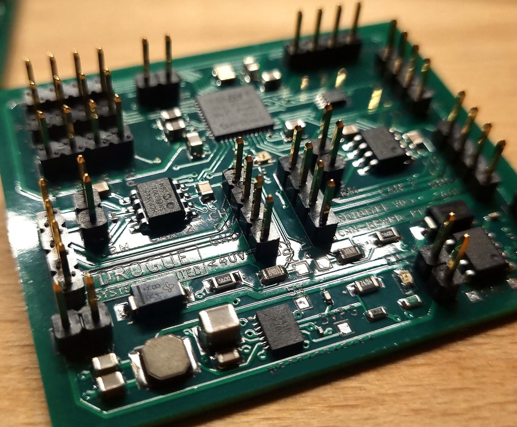
I am currently working on developing a set of CAN enabled microcontrollers and electronics. One of my first stepping stones is a dev board which I’m using both for hardware design verification and software development.
The first version (V0.1) of the dev board is now with me. I have a small few of these available to me, and I’d be willing to send a couple out to someone who is actively developing with Cyphal - and could make use of a dev board like this - to provide feedback on any emergent problems and suggestions on improving the design.
STM32G491 MCU (up to 168MHz, 8MHz external oscillator)
~53mm x 44mm small dimensions
2x FDCAN interfaces (MCP2542FDT) - without common mode choke so limited to ~1Mbps
(STM32G491 FDCAN interfaces are ISO 11898-1 compliant)
Optional 120ohm termination on each CAN bus with pin jumpers, controllable enable pins for each transceiver.
Dual independant power inputs up to 40V each (one power input grouped with each CAN bus)
2 sets of pins for each CAN bus and power input (easily place the board in line with bus with no(?)/tiny effective stub)
Voltage measuring of both power inputs with onboard ADC
32Kbit i2c EEPROM (128 pages x 32 bytes) for program accessible persistent storage
SW programming interface (ST-Link) with SWO debug line exposed
Exposed pins [PA0,1,2,3,4,5,6,7] [PB4,6,8,9,11] allows for simultanious 6x timer channels, SPI, 2x UART (one LPUART, one USART)
2x 5v, 2x 3.3V and 3x GND pins available for general use. Both rails have ~500mA (cumulative) available to external devices.
For better - or worse - I’ve used fairly new parts for this like the G4 series mcu, so there are some current limitations in tool availability - ie lack of easy PlatformIO project creation. But there is support in libopencm3 and of course all the HAL, LL and CMSIS usuals are there, and I’m sure theres plenty of others. - I am yet to begin developing any software or drivers to help support Cyphal integration on this.
There are also a few problems / issues already slated for remedy the next design:
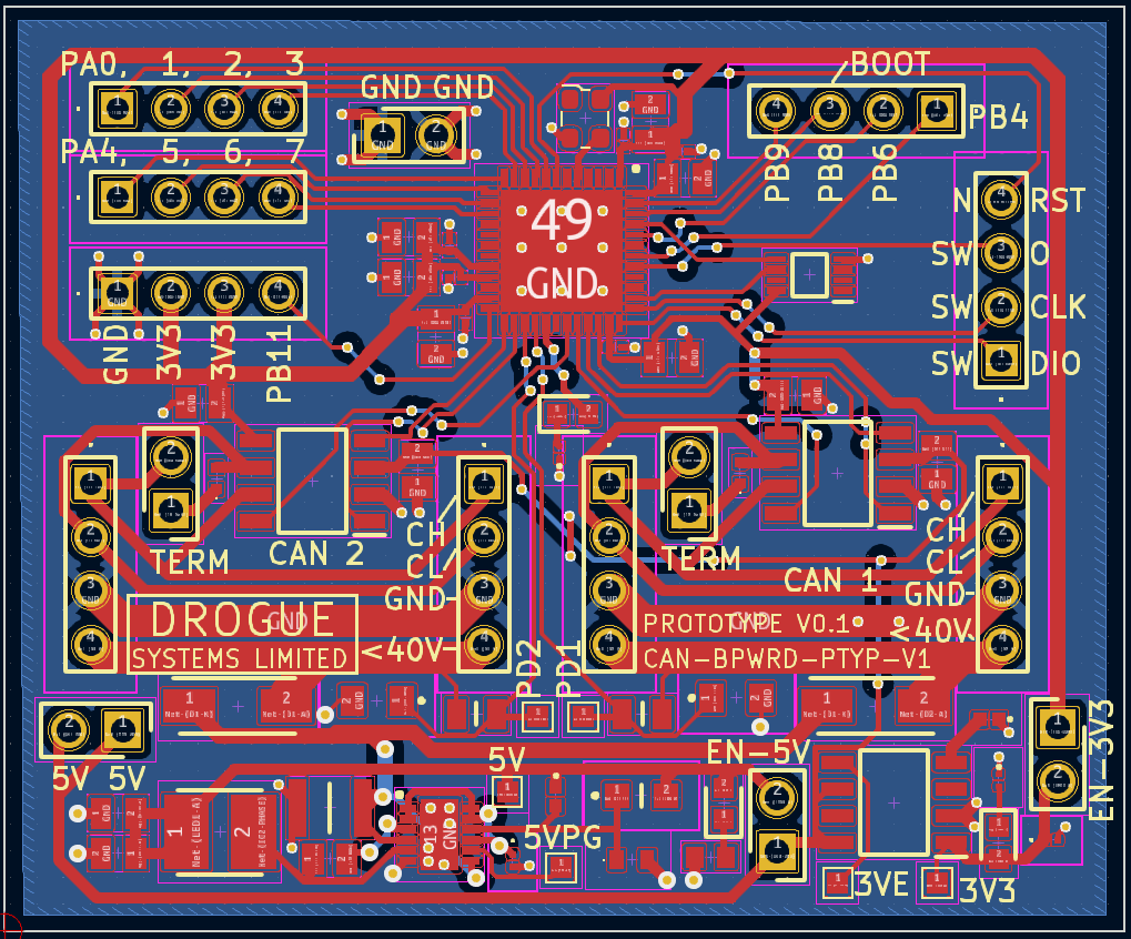
silk screen (PCB text) is the wrong colour. The board was originally meant to be white but had to be switched to green - the text was missed.
USB interface & USB programming would be superior to ST-Link programming and would better reflect deployed products
LED resistor values - The LED’s are bright - there is also an LED on pin PC6, however its use has to be prohibited in V0.1 as the resistor is incorrect and draws too much current from the mcu.
Power inputs to be fused - to align with physical specification
Also, just a note for discussion. I’m not sold on putting JST connectors on this board, as then to fit with the spec, it would then be restricted to 5V power supply on the bus, where as being a dev kit I feel that allowing a broad power input range will allow for developing electronics for all bus types. And the larger connectors (DSUB, M8) would themselves be quite large in comparison with the rest of the board. I’m not sure on the route to go down here, I’d be happy keeping it independant from the spec connectors and making some kind of way for adapting to each type maybe?
If anyone thinks they could benefit from trying this out and would be happy to provide good feedback, please let me know and I can have a look into getting one sent out. - please understand I really only do have a few and they weren’t particulary cheap for me to procure in a small batch, so I may not be able to say yes to anyone / everyone who replies unless im confident I will get some good feedback and/or the board may be useful.
Also, if anyone has any points, wants, etc they think could apply to the next version, please also let me know. I’m pretty open to design changes.
This is great. I have a little proposal for you, which I am going to share via PM.
Are you also interested in supporting Cyphal/UDP via multi-drop Ethernet in your design? Multi-drop (bus) 10BASE-T1S is huge and I expect it will largely displace CAN FD/XL from many markets that are relevant to us. @aentinger is already working on a dev board for Arduino that supports multi-drop Ethernet along with CAN FD.
Soldering connectors via wires is always an option and gives you the flexibility you’re looking for: use the same PCB with different connector options. In the case of M8, panel-mounted connectors can be used to facilitate high ingress protection ratings.
10BASE-T1S definietly looks like it could be the future. I quite like the philosophy of applying to the UxV industry what the automotive industy has shown to work well - ie CAN, and if uptake of 10BASE-T1S is as high as some expect, then I can see that being an appropriate route.
The STM32 mcu on this board doesnt support ethernet natively, but there are some 10BASE-T1S chips which make use of SPI and a few other pins which could be fairly easily applied to the design - perhaps even without losing the redundant FDCAN. It would be fairly easy to make a few different versions with different configurations and redundancies.
I’m happy you’ve followed through with building actual hardware . As you mention PlatformIO, are you planning to utilize 107-Arduino-Cyphal?
@pavel.kirienko : I’m not sure which board you refer too, there is OpenCyphalPicoBase with an Ardunio firmware stack which is CAN only at the moment, and there’s Pika Spark (sorry, no official picture yet ) which has 1 x 1000BASE-T, 1 x 10BASE-T1S, 2 x CAN/CAN FD, 2 x RS485, WiFi and IMU but is rather a fully fleged micro robot control unit running Linux and ROS (and not bare-metal).
Looking forward to see this project evolve. Hardware supported CAN/CAN FD (i.e. not via SPI connected transceiver) is certainly the right choice to make.
Really I just like PlatformIO in general - and it lets me get away from the CubeIDE and its a nice toolset for easy deployment.
More than happy to try running Arduino framework and 107-Arduino-Cyphal, just did a quick search I can see that there are libraries like ACANFD_STM32 which can already leverage the FDCAN peripherals in an STM32 so there really should be minimal struggle getting it working other than the effort of making a new board and paltform in PlatformIO.
Really the board is just aimed at being a development piece, so I plan to provide basic examples in a few different frameworks.
just wanted to post an update. The development boards have now had all thier peripherals tested and a hardware revision will be arriving soon.
Documentation is well under way (although still a work in progress), hosted here docs.drogue.co.uk
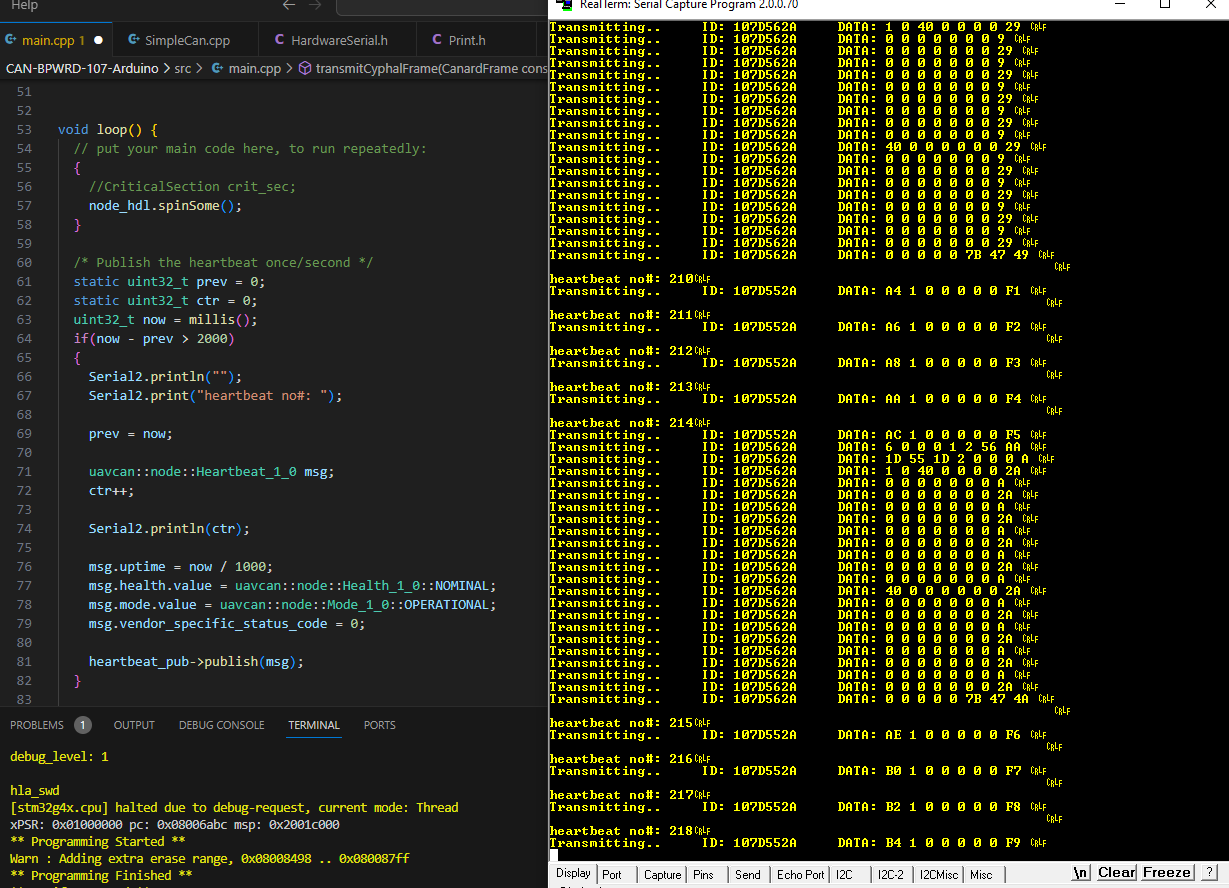
The 107-Arduino-Cyphal heartbeat example code seems to be running fine in the arduino framework on the STM32. Just running the basic node and serialisation at the moment and a mimic output instead of CAN. But it should be very simple from here to finish off that implementation - I just need to sort out some bit timing code.